In the realm of digital electronics and computer science, multiplexers, encoders, and decoders are fundamental building blocks that play pivotal roles in data manipulation, signal routing, and information processing. These components form the backbone of various digital systems, ranging from simple circuits to complex computational architectures. By efficiently managing data flow, optimizing signal distribution, and enabling effective communication between different parts of a system, multiplexers, encoders, and decoders contribute to the functionality and efficiency of modern electronic devices.
Multiplexers: Streamlining Data Transmission A multiplexer, often abbreviated as “mux,” is a digital device designed to consolidate multiple input signals into a single output. Think of it as a traffic controller for data, selecting one input among many and transmitting it to the output line. Multiplexers are widely used in scenarios where multiple data sources need to share a common communication channel, such as in telecommunications, data transmission, and memory addressing. By switching between inputs based on control signals, multiplexers optimize data transmission efficiency and conserve resources.
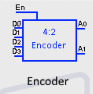
Encoders: Condensing Information An encoder is a digital circuit that converts multiple input signals into a smaller set of output signals. Unlike multiplexers, which only choose one input to transmit, encoders reduce complex data inputs into a simpler representation. Encoders are commonly employed to convert data from various sources into binary or Gray code formats, facilitating data compression, error detection, and data reduction tasks. They are particularly valuable in applications such as remote controls, digital sensors, and data compression algorithms.
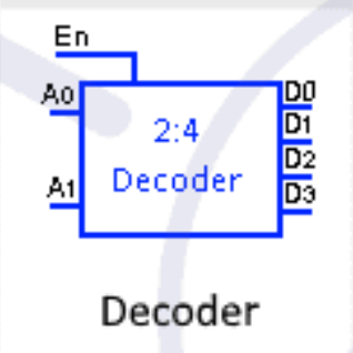
Decoders: Unraveling Information Decoders are counterparts to encoders, designed to reverse the encoding process. They take compressed or encoded data and restore it to its original format. By interpreting encoded signals and generating corresponding outputs, decoders enable effective communication between different parts of a system. Decoders are integral to operations like memory addressing, display control, and instruction decoding in microprocessors. They help translate abstract data representations into actionable commands, making them essential components in digital devices.
In this exploration of multiplexers, encoders, and decoders, we will delve into the principles that underlie their operations, their various applications across industries, and their significant contributions to the field of digital electronics. By understanding how these components manipulate and manage data, we gain insights into the intricate workings of digital systems that power our modern technological landscape.
Basic Multiplexer Operation
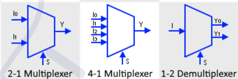
A multiplexer, often referred to as a “mux,” is a digital device that combines multiple input signals into a single output signal. It operates based on control signals that determine which input signal is selected for transmission to the output. This versatile component is widely used in digital circuits to streamline data transmission, optimize resource utilization, and facilitate efficient communication within electronic systems.
Key Components of a Multiplexer: A basic multiplexer consists of the following key components:
- Input Lines: These are the data input lines where different signals are fed into the multiplexer. The number of input lines depends on the design of the multiplexer and is usually a power of 2 (2, 4, 8, etc.).
- Control Lines: Control lines, often referred to as “select lines,” determine which input line is chosen to be transmitted to the output. The number of control lines depends on the number of input lines. For example, a 4-to-1 multiplexer has 4 input lines and requires 2 control lines to select one of the input lines.
- Output Line: This is the single output line where the selected input signal is transmitted.
Working Principle: The operation of a multiplexer is based on the concept of data selection. The control lines determine which input signal is chosen to be transmitted to the output. The binary values on the control lines dictate the selection of the corresponding input line. For instance, if there are two control lines, they can represent four possible combinations (00, 01, 10, 11), allowing selection among four input lines.
Here’s a step-by-step breakdown of how a multiplexer works:
- The control lines’ binary values determine which input line is selected.
- The selected input signal is transmitted to the output line.
- All other input signals are effectively disconnected from the output line.
Truth Table: A truth table is often used to illustrate the behavior of a multiplexer. It lists all possible combinations of control line inputs and indicates which input line is selected for each combination.
Applications: Multiplexers are used in various applications, including:
- Communication Systems: In telecommunications, multiplexers enable multiple signals to share a single communication channel, optimizing bandwidth usage.
- Memory Addressing: Multiplexers assist in selecting memory addresses, enabling efficient data storage and retrieval.
- Arithmetic Logic Units (ALUs): In CPUs, multiplexers route inputs to the appropriate ALU operation.
- Data Routing: Multiplexers direct data flow in digital systems, such as data buses in computers.
- Analog-to-Digital Converters (ADCs): Multiplexers select different analog input signals to be converted to digital values in ADCs.
Basic multiplexer is a crucial building block in digital circuit design that efficiently manages data streams by selecting one of several input signals for transmission to a single output line. Its versatility and widespread usage make it an integral component in various electronic systems, contributing to their functionality and efficiency.
Types of Multiplexers
Multiplexers (muxes) come in various configurations to suit different data routing and selection needs in digital systems. The type of multiplexer chosen depends on the number of input lines, the required number of control lines, and the specific application. Here are some common types of multiplexers:
- 2-to-1 Multiplexer: This is the simplest form of a multiplexer. It has two input lines, one output line, and one control line. The control line determines which of the two input lines is selected and transmitted to the output.
- 4-to-1 Multiplexer: A 4-to-1 multiplexer has four input lines, one output line, and two control lines. The two control lines provide four possible combinations to select one of the four input lines for output.
- 8-to-1 Multiplexer: With eight input lines and three control lines, an 8-to-1 multiplexer can choose one of the eight inputs to be transmitted to the output.
- 16-to-1 Multiplexer: This type of multiplexer has sixteen input lines and four control lines, enabling the selection of one input among sixteen.
- n-to-1 Multiplexer: Generalized multiplexers have a larger number of input lines (n) and the corresponding number of control lines to select one input among many. The number of control lines is given by ⌈log₂n⌉, where ⌈x⌉ denotes the ceiling function.
- 8-to-3 Multiplexer: This variant of a multiplexer has eight input lines, three control lines, and one output line. It selects one of the eight inputs based on the combination of control signals and transmits it to the output.
- Dual 4-to-1 Multiplexer: This type consists of two independent 4-to-1 multiplexers sharing the same control lines. It is useful when two different sets of data need to be multiplexed using the same control signals.
- 16-to-4 Multiplexer: A 16-to-4 multiplexer has sixteen input lines, four control lines, and four outputs. It can select one input out of sixteen and transmit it to one of the four outputs.
- Priority Encoder: Although not a traditional multiplexer, a priority encoder can be thought of as a type of multiplexer. It takes multiple input lines and encodes them into a binary code, identifying the highest-priority active input.
These various types of multiplexers are employed in different applications, from data communication and memory addressing to digital signal processing and arithmetic operations within integrated circuits. By selecting the appropriate multiplexer type, designers can efficiently manage data flows and optimize the operation of complex digital systems.
Multiplexer Cascading
Multiplexer cascading is a technique in digital circuit design that involves connecting multiple multiplexers together to create a more complex data selection mechanism. This approach expands the capabilities of simple multiplexers and enables the routing of data from multiple sources to various destinations with increased flexibility. Multiplexer cascading is used to build larger multiplexers, implement more sophisticated data routing schemes, and efficiently manage complex data flows within digital systems.
Why Use Multiplexer Cascading?
The need for multiplexer cascading arises when a single multiplexer’s capacity is insufficient to handle the number of input sources or destinations required by a specific application. Instead of designing and fabricating larger multiplexers, which can be more complex and costly, designers use cascading to achieve the desired functionality while maintaining modularity and simplicity.
Cascading Techniques:
- Input Cascading: In this technique, multiple smaller multiplexers are connected together to expand the number of input lines. The output of one multiplexer becomes an input for the next one. This allows handling a larger number of input sources. For example, two 4-to-1 multiplexers can be cascaded to create an 8-to-1 multiplexer.
- Output Cascading: Output cascading involves connecting the output of one multiplexer to the control lines of another. This allows selecting both an input line and an output line from a set of options. This technique is used to route data from multiple sources to multiple destinations.
- Input-Output Cascading: This technique combines the principles of both input and output cascading. It enables the selection of input and output lines based on control signals. Input-output cascading is especially useful when dealing with complex routing scenarios.
Benefits and Applications:
Multiplexer cascading offers several benefits:
- Modularity: Instead of designing a single large multiplexer, designers can use smaller multiplexers and connect them as needed, promoting modularity in circuit design.
- Flexibility: Cascading allows for more flexible data routing and selection, accommodating diverse requirements within a digital system.
- Resource Optimization: By using cascading, designers can efficiently utilize available resources while minimizing waste.
Multiplexer cascading finds applications in various fields:
- Arithmetic Logic Units (ALUs): Cascading multiplexers within an ALU allows for efficient selection of operations and operand sources.
- Data Routing in Networks: In networking equipment, cascaded multiplexers manage data packets, enabling proper routing and transmission.
- Microprocessor Control Units: Cascading is used to select specific instructions, operands, and data paths within the control unit.
- Digital Signal Processing: In signal processing applications, cascading multiplexers is essential for selecting different processing paths.
Multiplexer cascading is a powerful technique that enhances the capabilities of basic multiplexers, enabling designers to manage complex data flows and achieve more advanced functionalities in digital systems.
Multiplexer vs. Demultiplexer
Multiplexers and demultiplexers are fundamental digital components used in various applications to manage data transmission, distribution, and routing. Despite their similar-sounding names and roles in data manipulation, they serve distinct purposes in digital circuits. Let’s explore the key differences and functions of multiplexers and demultiplexers.
Multiplexer: A multiplexer, often abbreviated as “mux,” is a device that combines multiple input signals into a single output line. It uses control signals to select one of the input signals for transmission to the output. The primary purpose of a multiplexer is to efficiently utilize data communication channels and optimize data transmission by selecting the appropriate input signal based on control inputs.
Key Characteristics of a Multiplexer:
- Input Lines: Multiple input lines where data signals are fed.
- Output Line: A single output line where the selected input signal is transmitted.
- Control Lines: Control lines, also known as “select lines,” determine which input signal is chosen for output.
- Function: Data selection and routing.
Applications of Multiplexers:
- Telecommunications: Multiplexers enable multiple data signals to share a single communication channel, maximizing the utilization of available bandwidth.
- Memory Addressing: They assist in selecting memory addresses, optimizing data storage and retrieval.
- Data Routing: Multiplexers efficiently manage data flow in digital systems, such as computer data buses.
- Analog-to-Digital Conversion: Multiplexers select analog input signals for conversion in analog-to-digital converters (ADCs).
Demultiplexer: A demultiplexer, commonly known as “demux,” performs the opposite function of a multiplexer. It takes a single input signal and distributes it to one of several output lines based on control signals. Demultiplexers are used to route a single input signal to the appropriate destination among multiple possible destinations.
Key Characteristics of a Demultiplexer:
- Input Line: A single input line carrying the data signal.
- Output Lines: Multiple output lines where the input signal is routed based on control inputs.
- Control Lines: Control lines determine which output line receives the input signal.
- Function: Data distribution and routing.
Applications of Demultiplexers:
- Data Distribution: Demultiplexers distribute a single input signal to different parts of a system, ensuring data reaches the appropriate destination.
- Memory Selection: In memory systems, demultiplexers help select specific memory cells for reading or writing.
- Display Control: Demultiplexers route data to different segments of a display, such as in 7-segment displays.
- Address Decoding: Demultiplexers assist in decoding memory addresses or instruction addresses in microprocessors.
Multiplexers and demultiplexers are complementary components in digital circuits. While multiplexers consolidate multiple inputs into a single output, demultiplexers distribute a single input to multiple outputs. Understanding the distinctions between these two components is essential for designing efficient data routing, selection, and distribution mechanisms within digital systems.
Basic Encoder Types
Encoders are essential digital devices that convert multiple inputs into a binary code or digital output based on a set of rules. They are commonly used for data compression, error detection, and data reduction in various digital applications. Encoders play a crucial role in converting complex input patterns into simplified formats for efficient processing and transmission. Here are some of the basic types of encoders:
1. Priority Encoder: A priority encoder is used to encode multiple binary inputs into a binary code, prioritizing the highest-order active input. In cases where multiple inputs are active simultaneously, the priority encoder ensures that only the highest-priority input is encoded. Priority encoders are valuable for tasks such as interrupt handling in microcontrollers and selecting the most significant data in data acquisition systems.
2. Decimal-to-Binary Encoder: Decimal-to-binary encoders convert decimal digits (0-9) into their binary equivalents. They are useful in applications where decimal data needs to be processed using binary arithmetic, such as in digital displays, calculators, and digital signal processing.
3. BCD-to-Seven-Segment Decoder: Binary-Coded Decimal (BCD) encoders convert decimal digits into binary, typically for use in seven-segment displays. These displays are commonly used to represent numerical values in digital clocks, counters, and electronic signage. BCD encoders allow direct control of each segment in the display.
4. Octal-to-Binary Encoder: Octal-to-binary encoders convert octal digits (0-7) into binary format. They are useful for applications that involve processing octal data within digital systems, such as memory addressing or data storage.
5. Gray Code Encoder: Gray code encoders are designed to convert binary inputs into Gray code outputs. Gray code is a binary numeral system where adjacent values differ in only one bit, minimizing errors in digital systems that involve rotary encoders, position sensing, or communication between binary and analog systems.
6. Address Encoder: Address encoders are commonly used in memory systems to convert binary memory addresses into a format suitable for addressing specific memory locations. They are integral to efficient memory management in microcontrollers and microprocessors.
7. Data Encoders: Data encoders convert various data patterns into binary codes. They are employed in data transmission systems to compress data before transmission, reducing bandwidth requirements and enhancing transmission efficiency.
8. Priority Data Encoders: Similar to priority encoders, these devices encode data patterns, but they prioritize the most significant data. They are useful in situations where data needs to be processed or transmitted based on its significance.
Applications: Encoders find applications in a wide range of domains, including:
- Communication Systems: Encoders compress data for efficient transmission over communication channels.
- Error Detection: Encoders assist in generating error-detection codes to identify transmission errors.
- Digital Displays: Encoders convert data for display on various digital devices.
- Data Compression: Encoders compress data before storage or transmission to save space and resources.
- Microcontroller/Microprocessor Interfaces: Encoders prepare data for processing in digital systems.
Encoders simplify data representation and manipulation, contributing to the functionality and efficiency of digital systems across various industries.
Priority Encoding
Priority encoding is a digital circuit technique used to convert multiple input lines into a binary code that represents the highest-priority active input. This technique is commonly employed in applications where multiple inputs can be active simultaneously, and it’s necessary to identify the most significant or urgent input. Priority encoding is particularly valuable in interrupt handling, data multiplexing, and control systems where quick and accurate decision-making is crucial.
Basic Principle: The core principle of priority encoding is to identify the most significant active input and generate a binary code that represents its priority level. When multiple inputs are active at the same time, only the highest-priority input is encoded, and the others are disregarded.
Components: A priority encoder circuit typically consists of the following components:
- Input Lines: These are the input signals that need to be encoded based on their priorities.
- Priority Encoder Logic: This logic circuitry analyzes the input signals and determines which input has the highest priority.
- Priority Encoder Outputs: These outputs represent the binary code that corresponds to the highest-priority active input. The number of outputs is determined by the number of input lines.
- Control Logic: In some cases, control logic may be added to manage the encoding process and ensure proper operation.
Applications: Priority encoding has a variety of applications in digital systems:
- Interrupt Handling: In microcontrollers and processors, priority encoders are used to manage interrupt requests from various sources. The highest-priority interrupt is serviced first, ensuring critical tasks are addressed promptly.
- Data Multiplexing: In multiplexer control circuits, priority encoding helps select the most important data source when multiple inputs are requesting access to a single output line.
- Control Systems: Priority encoding is used in control systems to prioritize actions or decisions based on the urgency or significance of different inputs.
- Task Scheduling: In scheduling algorithms and real-time systems, priority encoding aids in selecting the most time-sensitive task for execution.
Example: Let’s consider a priority encoder with four input lines (A, B, C, D). If more than one input is active, the encoder will prioritize them in the order A > B > C > D. If both A and B are active, the output will be ’00’ (binary) to represent input A’s priority. If only input C is active, the output will be ’01’, and so on.
Advantages:
- Priority encoding simplifies decision-making by focusing on the most significant input.
- It enables efficient handling of time-critical tasks and events.
- Priority-encoded data can be easily processed further in digital systems.
Limitations:
- Priority encoding might not capture the nuances of all inputs’ relative importance; it only represents the highest-priority input.
- More complex priority encoding schemes might be needed for applications with complex prioritization rules.
Priority encoding is a valuable technique in digital circuit design that helps identify and encode the most significant input among a set of active inputs. It ensures efficient utilization of resources and timely response to critical events in various digital systems.
Applications of Encoders
Encoders are versatile devices used in a wide range of applications to convert different types of input signals into digital or binary formats. Their ability to simplify data representation, provide accurate measurements, and enable efficient data processing makes them indispensable in various industries. Here are some key applications of encoders:
1. Rotary Encoders: Rotary encoders are used to measure the angular position, velocity, and direction of rotation of mechanical shafts. They find applications in:
- Robotics: Rotary encoders provide feedback to control the movement and position of robot joints.
- CNC Machines: Encoders aid in precision control of machine tool movements.
- Printers and Plotters: Rotary encoders ensure accurate paper feeding and printing.
- Automotive: Encoders are used in vehicle systems like throttle position sensors and steering wheel angle detection.
2. Absolute Encoders: Absolute encoders provide a unique digital code for each position, allowing accurate positioning without requiring a reference point. Applications include:
- Elevators: Absolute encoders ensure precise floor-level detection and control.
- Medical Equipment: They are used in equipment like medical scanners and radiation therapy devices.
- Aerospace: Encoders play a role in position feedback for flight control surfaces.
3. Incremental Encoders: Incremental encoders provide pulses corresponding to the incremental movement of a shaft. They are used in:
- Motor Control: Incremental encoders offer feedback for controlling motor speed and position.
- Conveyor Systems: They monitor conveyor belt movement and control material handling.
- Packaging Machines: Encoders are used to measure the amount of material dispensed in packaging.
4. Optical Encoders: Optical encoders use light-based systems to detect position changes. They are used in applications where precision is crucial:
- Photography Equipment: They help in accurately positioning camera mechanisms.
- Telescope Mounts: Encoders enable precise positioning of telescope mounts for astronomical observations.
- Laser Cutting Machines: Optical encoders assist in precise material cutting.
5. Digital Audio Equipment: Encoders are used in audio equipment for tasks like volume control, channel selection, and user interface navigation.
6. Consumer Electronics: Encoders are present in various consumer devices such as remote controls, digital cameras, and gaming consoles, enabling user input and interaction.
7. Automation and Robotics: Encoders provide essential feedback to control the position and movement of robotic arms, conveyors, and automated systems.
8. Aerospace and Defense: Encoders are used in aviation for cockpit controls, missile guidance systems, and satellite positioning.
9. Medical Devices: Encoders play a role in medical imaging devices, robotic surgery systems, and patient monitoring equipment.
10. Process Control and Manufacturing: Encoders are integral to control systems in industries like manufacturing, food processing, and chemical processing.
11. Industrial Automation: Encoders help monitor and control the movement of equipment in industrial automation setups.
12. Energy Generation: Encoders are used in wind turbines, hydroelectric generators, and solar tracking systems to monitor position and movement.
Encoders are essential components in a wide array of applications, contributing to accurate measurement, precise control, and efficient data processing across various industries. Their ability to convert physical parameters into digital signals enhances the functionality and performance of modern technologies.
Encoders vs. Decoders
Encoders and decoders are essential digital components that serve complementary roles in the manipulation and transformation of data within digital systems. While both are used to process and represent data, they operate in distinct ways to achieve different objectives. Let’s delve into the differences and functions of encoders and decoders:
Encoders:
Function: Encoders take multiple input signals and encode them into a binary code or a simplified digital output. The primary purpose of an encoder is to represent data in a more efficient or manageable form, often for purposes like data compression, error detection, and data reduction.
Operation: Encoders accept various types of input signals, such as binary, decimal, or analog data, and convert them into a binary representation. This representation is usually simpler and more suitable for digital processing.
Types: Encoders come in various types, including priority encoders, decimal-to-binary encoders, BCD-to-seven-segment decoders, Gray code encoders, and more. Each type is designed to address specific data transformation requirements.
Applications: Encoders find applications in diverse fields, such as communication systems for data compression, digital displays for BCD-to-seven-segment conversion, and control systems for encoding sensor data.
Decoders:
Function: Decoders take binary-encoded input signals and produce an output based on a set of rules or decoding logic. The primary role of a decoder is to interpret encoded data and restore it to its original format or perform specific actions based on the input.
Operation: Decoders analyze the binary input code and produce a specific output pattern corresponding to the encoded input. This process involves mapping binary patterns to specific outputs.
Types: Decoders are categorized based on the number of inputs and outputs they have, such as 2-to-4 decoders, 3-to-8 decoders, and more. Decoders like BCD-to-seven-segment decoders translate binary-coded decimal inputs to outputs for seven-segment displays.
Applications: Decoders are used in various applications, including memory addressing in digital systems, display control for seven-segment displays, and instruction decoding in microprocessors.
Key Differences:
- Function: Encoders encode input signals into a simplified format, while decoders interpret encoded data and generate corresponding outputs.
- Input Signals: Encoders accept various types of input signals (binary, decimal, analog) and transform them into binary-encoded outputs. Decoders, on the other hand, primarily work with binary-encoded inputs.
- Output Signals: Encoders produce binary-encoded outputs, whereas decoders generate specific output patterns based on the input code.
- Application Focus: Encoders are focused on data representation and manipulation for efficiency, compression, and reduction. Decoders are focused on data interpretation and action based on the input code.
- Types: Encoders have various types based on their functions, while decoders are often categorized by the number of inputs and outputs.
Encoders and decoders are integral components in digital systems that serve distinct roles. Encoders transform data into efficient formats, while decoders interpret encoded data to trigger specific actions or restore the original data’s representation. Their combined functionality contributes to the effective manipulation and processing of data in digital applications.
Basic Decoder Types
Decoders are fundamental digital devices that take binary input signals and produce one or more output signals based on the input code. These devices play a critical role in various digital systems by interpreting encoded information and enabling specific actions or data routing. Here are some basic types of decoders:
1. Binary Decoder (2-to-4 Decoder): A binary decoder, often referred to as a 2-to-4 decoder, takes a binary input consisting of two bits and generates four possible output combinations. Each output corresponds to one of the binary input values (00, 01, 10, 11). Binary decoders are commonly used for memory addressing in digital systems, where they select one of several memory locations based on the binary address.
2. 3-to-8 Decoder: A 3-to-8 decoder accepts a 3-bit binary input and produces eight possible output lines. Each output line represents one of the eight binary values that can be formed with three bits (000 to 111). This type of decoder is useful in applications such as data routing and selection, where it allows for eight different data paths to be selected based on the input code.
3. 4-to-16 Decoder: A 4-to-16 decoder has four input lines and sixteen output lines, making it capable of decoding all possible 4-bit binary input combinations (0000 to 1111). This type of decoder is employed in more complex data routing scenarios, where sixteen different output selections are needed based on the input code.
4. BCD-to-Decimal Decoder: BCD-to-decimal decoders are designed specifically to convert Binary-Coded Decimal (BCD) inputs into their decimal equivalents. In BCD representation, each decimal digit is represented by a 4-bit binary code. These decoders are frequently used in applications like seven-segment display control, where BCD inputs are converted into the appropriate signals to display decimal numbers.
5. Priority Decoder: A priority decoder takes multiple input lines and determines which input line has the highest priority or is active. It then generates an output code corresponding to the highest-priority input. Priority decoders are often used in microprocessor interrupt handling, where they prioritize and respond to various interrupt requests.
6. 2-to-1 Line Multiplexer (Multiplexing Decoder): Although not a traditional decoder, a 2-to-1 line multiplexer can be thought of as a type of decoder. It has two input lines and a control input. Depending on the control input, it selects one of the two input lines to pass through to the output. This operation can be viewed as decoding the control input to choose between the two data inputs.
Applications: Decoders are essential components in digital systems with various applications, including:
- Memory Addressing: Decoders select specific memory locations based on binary addresses.
- Seven-Segment Displays: BCD-to-decimal decoders convert binary inputs to decimal digits for display.
- Instruction Decoding: In microprocessors, decoders interpret instruction opcodes to execute specific operations.
- Data Routing: Decoders route data to the appropriate destination based on input codes.
- Control Systems: Priority decoders are used to manage interrupt requests and prioritize tasks.
- Data Multiplexing: Multiplexing decoders are used to select data sources for output.
These basic decoder types form the building blocks of more complex digital systems, enabling the interpretation and manipulation of encoded data for various applications across different industries.
Decoding Logic
Decoding logic is a crucial aspect of digital circuit design that involves transforming encoded input signals into meaningful outputs or actions. Decoders are central to this process, as they interpret binary-encoded data and generate specific output patterns based on the input code. Decoding logic enables efficient data processing, control, and communication within digital systems. Let’s explore the fundamentals of decoding logic and its significance in various applications.
The Role of Decoders: Decoders serve as the bridge between encoded data and actionable outcomes. They take binary inputs and determine which specific output pattern or action corresponds to the input code. Decoding logic is vital in scenarios where multiple inputs require distinct responses, such as in memory addressing, instruction execution, display control, and interrupt handling.
Working Principle: Decoding logic operates by analyzing the binary input code and activating the appropriate outputs or actions based on predetermined rules. Each possible input code corresponds to a specific output pattern, which could involve activating certain control signals, triggering operations, or selecting data paths. Decoding logic is implemented using combinations of logic gates, such as AND gates, OR gates, and inverters, to map input codes to corresponding output patterns.
Types of Decoding Logic: Several types of decoding logic are used based on the complexity of the input-output relationship and the specific application requirements:
- Binary Decoding: Simplest form of decoding logic, where binary inputs map directly to specific outputs. Binary decoders are used in memory addressing and data routing.
- BCD-to-Decimal Decoding: Converts Binary-Coded Decimal (BCD) inputs to their decimal equivalents for display on seven-segment displays or other decimal output formats.
- Priority Decoding: Determines the highest-priority active input and generates an output corresponding to that priority level. Often used in interrupt handling.
- Address Decoding: Used to select specific memory locations or peripheral devices based on binary address inputs.
- Instruction Decoding: In microprocessors, opcode decoding logic interprets instruction codes to execute specific operations.
Applications: Decoding logic is pervasive across various domains:
- Memory Systems: Address decoding selects memory locations for read or write operations.
- Digital Displays: Decoding logic converts binary inputs to appropriate signals for display control.
- Microprocessors: Instruction decoding determines the operations to be executed.
- Control Systems: Decoding logic manages interrupts, prioritizes tasks, and controls actuators.
Significance: Decoding logic plays a fundamental role in the functionality and efficiency of digital systems. It enables machines to interpret and respond to user input, external events, and internal processes. Decoding logic allows digital systems to transform encoded data into actionable outcomes, making it a cornerstone of modern technology.
In essence, decoding logic is the brain of digital systems, responsible for translating binary codes into meaningful actions, decisions, and responses. Its strategic implementation is essential for ensuring accurate data processing, efficient control, and effective communication within complex digital architectures.
Decoder Implementations
Decoder implementations are critical in digital circuit design as they define how encoded data is interpreted and translated into meaningful outputs or actions. Decoders play a vital role in various applications, from memory systems and display control to microprocessor instruction decoding. Different approaches and strategies are used to implement decoders, each tailored to the specific requirements and complexity of the task at hand. Let’s explore some common decoder implementations:
1. Combinational Logic Decoder: A combinational logic decoder is the most straightforward implementation. It consists of a network of logic gates, such as AND gates and OR gates, that directly map binary input codes to specific output patterns. Combinational logic decoders are used when the relationship between input and output is simple and direct. Binary and BCD decoders often use this approach.
2. Read-Only Memory (ROM) Decoder: A ROM-based decoder involves using a read-only memory as a lookup table to store the mapping between input codes and output patterns. The inputs serve as the address lines for the ROM, and the corresponding outputs are stored at the respective addresses. This approach is effective when a complex input-output relationship needs to be implemented efficiently.
3. Multiplexer-Based Decoder: A multiplexer-based decoder uses multiplexers to select and route specific output signals based on the input code. This approach is particularly useful when a decoder needs to produce a few specific outputs from a larger set of possibilities. Multiplexers simplify the selection process by allowing direct control over output lines.
4. Programmable Logic Devices (PLDs): PLDs, such as Complex Programmable Logic Devices (CPLDs) and Field-Programmable Gate Arrays (FPGAs), can be programmed to implement complex decoding logic. These devices offer flexibility and configurability, making them suitable for applications where the decoding requirements may change or evolve over time.
5. Priority Encoder as a Decoder: In some cases, a priority encoder can be used as a decoder. By inverting the input lines and using the priority encoder’s outputs, the highest-priority input can be treated as the active input in a decoding process.
6. Multiplexing Decoder: A multiplexing decoder is a combination of a multiplexer and a decoder. It involves using multiplexers to select one of several outputs produced by a decoder circuit. This approach is useful when there’s a need to choose among a set of pre-encoded output patterns.
Applications of Different Implementations:
- Combinational Logic Decoders are used in applications where the decoding relationship is simple and straightforward.
- ROM Decoders are valuable for complex input-output mappings that need efficient implementation.
- Multiplexer-Based Decoders are suitable when only a subset of outputs is needed from a larger set.
- Programmable Logic Devices (PLDs) are versatile and can handle a wide range of decoding requirements.
- Priority Encoders can be repurposed as decoders when a priority-based approach is beneficial.
The choice of decoder implementation depends on factors such as the complexity of the input-output relationship, the number of inputs and outputs, and the available resources. Digital system designers carefully select the appropriate implementation to achieve accurate data interpretation, efficient resource utilization, and optimal performance.
Conclusion
Multiplexers, encoders, and decoders are fundamental building blocks of digital circuits that play pivotal roles in data manipulation, interpretation, and control within digital systems. Each of these components serves a distinct purpose and contributes to the efficiency, functionality, and versatility of modern technologies.
Multiplexers are used to select one of many input signals and route it to an output line. They are integral in data communication, memory addressing, and data routing scenarios, optimizing data flows and resource utilization.
Encoders transform input signals into binary codes, facilitating data compression, error detection, and data representation. Encoders are crucial for efficient data transmission, control systems, and various applications involving digital representation.
Decoders interpret binary-encoded data and generate specific outputs or actions based on the input code. They are essential for memory addressing, display control, microprocessor instruction execution, and interrupt handling.
Together, these components form the backbone of digital systems, enabling the translation, selection, and interpretation of data for numerous applications across diverse industries. Their implementations and applications are as varied as they are essential, ranging from basic memory addressing to sophisticated robotics, telecommunications, and control systems.
The dynamic interplay between multiplexers, encoders, and decoders showcases the adaptability and power of digital circuitry. As technology continues to advance, these components remain foundational, ensuring accurate data handling, efficient resource management, and responsive decision-making within the intricate world of digital design. Whether in simple circuits or complex systems, multiplexers, encoders, and decoders continue to shape the digital landscape, enhancing our ability to process information and interact with the digital world.