In the realm of digital electronics, where binary data and logic operations reign supreme, the concepts of flip-flops and counters stand as fundamental building blocks. These components play a pivotal role in storing and manipulating binary information, enabling the creation of memory units, sequential circuits, and devices that form the backbone of modern computing systems.
A flip-flop is a bistable multivibrator, a circuit capable of existing in one of two stable states and transitioning between them in response to external signals. It forms the bedrock of digital memory, storing a single bit of information in the form of a 0 or 1. Flip-flops provide the foundation for sequential logic circuits, where the output depends not only on the current input but also on the past inputs and internal states, leading to the concept of time-dependent logic operations.
Counters, on the other hand, extend the capabilities of flip-flops to create dynamic circuits that generate sequences of binary numbers. These sequences serve a multitude of purposes, from tracking events to providing clock signals for various components within digital systems. Counters can be synchronous, following the clock signal, or asynchronous, driven by external events. They find application in areas such as frequency division, digital clocks, event counting, and state machines, shaping the way digital devices perform and interact.
Understanding the intricate workings of flip-flops and counters is essential for anyone delving into digital design, computer architecture, or electronics engineering. This knowledge empowers engineers and designers to create efficient and reliable systems that process, store, and manipulate binary information accurately, forming the backbone of our technologically advanced world. In this exploration, we will delve deeper into the mechanisms, types, and applications of flip-flops and counters, unraveling the core principles that underpin their significance in the digital realm.
Types of Flip-Flops
Flip-flops are fundamental building blocks in digital electronics that store binary information. They come in various types, each designed with specific characteristics and applications in mind. These flip-flop types include:
- SR Flip-Flop (Set-Reset Flip-Flop): The SR flip-flop has two inputs – the Set (S) input and the Reset (R) input. It can be in one of two stable states: Set (Q = 1) or Reset (Q = 0). When both inputs are low, the flip-flop maintains its current state. The SR flip-flop is simple but can lead to unpredictable behavior when both inputs are high simultaneously.
- JK Flip-Flop: The JK flip-flop improves upon the SR flip-flop by addressing the problem of indeterminate states. It has three inputs: J (Set), K (Reset), and a clock input. The J and K inputs work together to control the flip-flop’s behavior. When both inputs are high, the flip-flop toggles its state on each clock pulse. JK flip-flops are widely used for their versatility and predictable behavior.
- D Flip-Flop (Data Flip-Flop): The D flip-flop has a single data input (D) and a clock input. It captures the input data and updates its output (Q) on the rising or falling edge of the clock signal. D flip-flops are commonly used for creating registers and storing data in sequential logic circuits.
- T Flip-Flop (Toggle Flip-Flop): The T flip-flop has a Toggle (T) input and a clock input. It toggles its state (Q) on each clock pulse when the T input is high, effectively dividing the input frequency by 2. T flip-flops are useful in creating frequency dividers and counters.
- Master-Slave Flip-Flop: This type of flip-flop consists of two interconnected flip-flops: a master and a slave. The master flip-flop captures the input data during the first half of the clock cycle, and the slave flip-flop updates its output based on the master’s state during the second half of the cycle. This configuration prevents glitches and provides a synchronized output.
- Edge-Triggered Flip-Flop: Edge-triggered flip-flops, including the rising-edge and falling-edge types, respond to changes in the clock signal rather than its continuous value. This ensures that the flip-flop state changes only at specific instances, reducing the chances of unintended transitions.
- Clocked SR Flip-Flop: This flip-flop type includes a clock input along with the set and reset inputs. The clocked SR flip-flop addresses the problem of the SR flip-flop’s indeterminate state by allowing changes in state only when the clock signal transitions.
- Gated D Latch: While not a flip-flop in the strictest sense, the gated D latch is a latch-based memory element that can be controlled by an enable signal. It is simpler than a flip-flop and is used in applications that require basic memory storage.
Each type of flip-flop has its own advantages and applications, and the choice of which one to use depends on the specific requirements of a given digital circuit. By understanding the characteristics and behaviors of these flip-flops, engineers and designers can select the most suitable component for their designs and ensure the reliability and functionality of their digital systems.
Flip-Flop Characteristics and Applications
Flip-flops are essential building blocks in digital electronics, providing the ability to store and manipulate binary information. They possess distinct characteristics that make them suitable for various applications across a wide range of industries. Let’s delve into some of the key characteristics and applications of flip-flops:
Characteristics:
- Bistable Operation: Flip-flops have two stable states, allowing them to store a single binary digit (0 or 1) of information. They can be triggered to switch between these states by specific inputs or clock signals.
- Edge Sensitivity: Many flip-flops are edge-triggered, responding to transitions (rising or falling edges) in the clock signal rather than its continuous state. This characteristic ensures that state changes occur precisely when needed.
- Synchronous Behavior: Flip-flops can be synchronous, meaning their state changes are synchronized with a clock signal. This synchronization is crucial for preventing timing issues and maintaining consistent operation in digital circuits.
- Sequential Logic: Flip-flops enable the creation of sequential logic circuits, where the output depends not only on the current input but also on the past inputs and internal states. This characteristic is vital for designing memory elements and state machines.
- Memory Storage: Flip-flops are used to store data in digital systems. By connecting multiple flip-flops together, data can be stored as bits in registers, forming the basis of memory units in computers and microcontrollers.
Applications:
- Registers: Flip-flops are the fundamental components of registers, which store data temporarily within a processor or microcontroller. Registers are essential for various operations, such as data manipulation, arithmetic calculations, and control tasks.
- Counters: Counters utilize flip-flops to generate sequences of binary numbers. These sequences are used for tasks such as counting events, creating clock signals of different frequencies, and implementing state machines in control systems.
- Clock Dividers: Flip-flops are employed in clock divider circuits, which generate lower-frequency clock signals from higher-frequency ones. This is useful for driving different components of a digital system with appropriate timing.
- State Machines: Complex systems often require sequential logic to respond to different inputs and events. Flip-flops play a crucial role in implementing state machines, which define the system’s behavior based on its current state and input conditions.
- Flip-Flop-Based Logic Gates: Flip-flops can be used to create various types of logic gates, such as SR latch-based NOR gates. These gates find application in memory cells, latch-based circuits, and signal processing.
- Digital Clocks: Flip-flops contribute to the generation and synchronization of digital clock signals used in processors, microcontrollers, and communication systems.
- Event Detection: Flip-flops are employed to detect and remember specific events in digital systems, allowing them to respond to particular conditions or triggers.
- Frequency Division: Flip-flops are utilized to divide the frequency of input signals, which is valuable for tasks like generating clock pulses at different rates.
Flip-flops are versatile components that serve as the backbone of digital electronics. Their distinct characteristics make them suitable for a wide range of applications, from simple memory storage to complex state machines. By understanding these characteristics and their applications, engineers and designers can effectively leverage flip-flops to create robust and efficient digital systems.
Flip-Flop Timing and Sequential Circuits
Timing is a critical aspect of digital electronics, especially in sequential circuits where the order of events and the synchronization of signals play a pivotal role. Flip-flops, as fundamental components of sequential circuits, exhibit specific timing characteristics that are crucial for ensuring proper functionality and avoiding issues such as glitches and race conditions. Understanding flip-flop timing is essential for designing reliable and predictable digital systems.
Clock Signals and Timing:
Flip-flops are often controlled by clock signals, which determine when the state of the flip-flop should change. The clock signal transitions (rising or falling edges) are used as triggers for updating the flip-flop’s output based on the input data. Proper synchronization of clock signals across all flip-flops is vital to prevent timing disparities and ensure consistent operation within a sequential circuit.
Setup and Hold Time:
Two critical timing parameters associated with flip-flops are the setup time and the hold time. The setup time is the minimum duration before the clock signal transition during which the input data must remain stable for proper data capture. The hold time, on the other hand, is the minimum duration after the clock signal transition during which the input data must remain unchanged.
Failure to meet the setup and hold time requirements can result in metastability – a temporary state where the flip-flop is unable to settle in either of its stable states, leading to unpredictable behavior. To prevent metastability, designers ensure that the input data is stable within the setup and hold time windows around the clock edge.
Propagation Delay:
Propagation delay refers to the time taken for the output of a flip-flop to transition after the input has changed. It is a critical parameter for ensuring that the outputs of sequential circuits change in a controlled and synchronized manner. When multiple flip-flops are connected in series, the cumulative propagation delays can affect the overall timing behavior of the circuit.
Synchronous vs. Asynchronous Circuits:
In synchronous circuits, all flip-flops are clocked by the same clock signal, ensuring that state changes occur simultaneously. This synchronous behavior simplifies timing analysis and reduces the chances of timing-related issues. Asynchronous circuits, on the other hand, lack a common clock and are driven by local signals or events. While they can provide certain advantages in terms of responsiveness, they are more complex to design due to the absence of a central timing reference.
Sequential Circuit Timing Analysis:
Designers use various techniques, such as timing diagrams and simulation tools, to analyze and verify the timing behavior of sequential circuits. Timing diagrams visually depict the relationships between clock signals, input data, and output responses over time. Simulation tools allow engineers to model and simulate the behavior of flip-flops and other circuit components under different conditions, helping identify and rectify timing issues.
In conclusion, flip-flop timing is a critical consideration in the design of sequential circuits. Proper synchronization of clock signals, adherence to setup and hold times, and careful analysis of propagation delays are essential for creating reliable and predictable digital systems. By mastering the intricacies of flip-flop timing, engineers can ensure that their designs function as intended and meet the demands of modern digital applications.
Synchronous Counters
Synchronous counters are a type of digital circuit that generates a sequence of binary numbers in response to clock pulses. Unlike asynchronous counters, where each flip-flop toggles independently based on its own output, synchronous counters utilize a common clock signal to synchronize the state changes of all flip-flops. This synchronized behavior ensures that the counter progresses through the desired sequence without glitches or timing-related issues.
Working Principle:
A synchronous counter is composed of a chain of flip-flops, typically D-type flip-flops, connected in a cascade fashion. The output of each flip-flop serves as the clock input for the next flip-flop in the chain. When a clock pulse arrives, all flip-flops change their states simultaneously, generating the next binary value in the sequence.
To create a binary sequence, the outputs of the flip-flops are treated as the binary bits. For a counter with ‘n’ flip-flops, the sequence generated will loop through all binary values from 0 to 2^n – 1 and then repeat. The initial state and the arrangement of the flip-flops determine the sequence and direction (up or down) of counting.
Advantages of Synchronous Counters:
- Predictable Timing: Synchronous counters are inherently predictable due to their synchronized operation. This eliminates the possibility of glitches or transient states that can occur in asynchronous counters.
- Easy State Analysis: Since all flip-flops change state simultaneously, the analysis of a synchronous counter’s state progression is straightforward. Timing diagrams and truth tables can be easily used to understand and verify the counter’s behavior.
- Uniform Clock Distribution: Synchronous counters use the same clock signal for all flip-flops, ensuring uniform distribution of timing across the circuit. This makes them suitable for applications that require precise timing synchronization.
Applications of Synchronous Counters:
- Frequency Division: Synchronous counters are often used as frequency dividers. By connecting the output of the last flip-flop to the input, the counter can divide the clock frequency by powers of 2, generating lower-frequency clock signals.
- Digital Clocks: Synchronous counters are used to generate digital clock signals with different frequencies for various components within a digital system. This is essential for coordinating different operations.
- Event Counting: Synchronous counters can be employed to count events or occurrences, such as the number of pulses from a sensor, button presses, or other digital inputs.
- Sequence Generation: Synchronous counters are used to generate specific sequences of binary values that are used in control logic or memory addressing.
- State Machines: Synchronous counters form the basis for implementing state machines, which are widely used in control systems and digital signal processing.
Synchronous counters provide a reliable and predictable way to generate binary sequences by using a common clock signal to synchronize the state changes of multiple flip-flops. This characteristic makes them well-suited for applications that demand precise timing synchronization and reliable operation, ranging from frequency division to controlling complex digital systems through state machines.
Asynchronous Counters
Asynchronous counters, also known as ripple counters, are a type of digital circuit that generates a sequence of binary numbers based on individual clock signals for each flip-flop. Unlike synchronous counters where all flip-flops change state simultaneously in response to a common clock pulse, asynchronous counters rely on the propagation of carry or ripple signals through the flip-flops. While they offer simplicity and flexibility, asynchronous counters are more prone to glitches and timing issues compared to their synchronous counterparts.
Working Principle:
An asynchronous counter consists of a chain of flip-flops, typically D-type flip-flops, connected in a cascade fashion. Each flip-flop’s clock input is connected to the output of the previous flip-flop. When a clock pulse arrives at the first flip-flop, it changes state, potentially triggering a carry signal to the next flip-flop. This process repeats through the chain, resulting in a binary sequence.
Advantages of Asynchronous Counters:
- Simplicity: Asynchronous counters require fewer components compared to synchronous counters, making them easier to design and implement.
- Flexibility: Since each flip-flop responds independently to its clock signal, asynchronous counters can be easily configured to generate specific count sequences, including non-binary sequences if desired.
Challenges of Asynchronous Counters:
- Timing Issues: Asynchronous counters are more susceptible to timing problems. Since each flip-flop responds to the previous one, variations in signal propagation times can lead to glitches, transient states, and unpredictable behavior.
- Glitches: The changing state of one flip-flop can cause glitches or unwanted transitions in the outputs of other flip-flops before the ripple signals settle.
- Propagation Delays: The propagation delay through the flip-flops can result in cumulative timing inaccuracies, limiting the maximum clock frequency that can be used.
Applications of Asynchronous Counters:
- Event Detection: Asynchronous counters can be used to count the occurrences of events, such as the number of pulses from a sensor, button presses, or other digital inputs.
- Decoding and Multiplexing: Asynchronous counters can be used in conjunction with decoding logic to create multiplexers and other combinatorial circuits.
- Frequency Division: While less commonly used for frequency division due to their potential timing issues, asynchronous counters can still be employed in some applications that don’t require high accuracy.
- Simple Counting Tasks: Asynchronous counters can be useful for simple counting tasks in situations where precise timing is not a critical concern.
Asynchronous counters provide a simpler and more flexible approach to generating binary sequences compared to synchronous counters. However, their susceptibility to timing issues and glitches makes them less suitable for applications that demand precise synchronization and reliable operation. Designers must carefully consider the trade-offs between simplicity and timing accuracy when choosing between synchronous and asynchronous counters for a particular application.
Decade Counters and BCD Counters
Decade counters and Binary Coded Decimal (BCD) counters are specialized types of counters used in digital electronics to generate specific counting sequences and to represent decimal numbers in binary form. They find applications in various fields, including digital clocks, industrial automation, and arithmetic circuits.
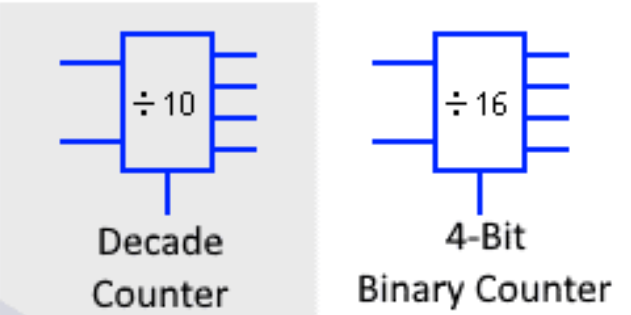
Decade Counters:
A decade counter is a counter that generates a sequence of ten unique states before resetting to its initial state. It typically counts from 0 to 9 in binary representation, which corresponds to a decimal range of 0 to 9. Decade counters are used in applications where the counting sequence should align with the decimal system.
BCD Counters:
Binary Coded Decimal (BCD) counters are designed to count in binary form while maintaining the capability to directly represent decimal digits. In BCD, each decimal digit is encoded using a 4-bit binary code. BCD counters generate a sequence of BCD values, which simplifies interfacing with decimal displays and devices.
Working Principle:
Both decade counters and BCD counters can be implemented using a combination of flip-flops, often using a combination of D-type flip-flops and logic gates.
Decade counters typically have four flip-flops, each representing a bit in the binary count. When the counter reaches 9 (1001 in binary), it generates a carry signal that resets the counter back to 0 (0000).
BCD counters also use four flip-flops, but they incorporate logic to ensure that the count sequence follows the BCD pattern. When the counter reaches 9 (1001 in BCD), it generates a carry that increments the next digit by one while resetting the current digit to 0.
Applications:
- Digital Clocks: Decade counters and BCD counters are often used in digital clock circuits to generate the count for seconds, minutes, and hours. The BCD format is convenient for driving displays that show decimal time.
- Industrial Counting Systems: These counters are used in industrial applications to count products, process steps, or events where the count needs to be displayed in a human-readable format.
- Frequency Dividers: Decade counters can be used as frequency dividers, generating output pulses at lower frequencies by counting a certain number of input pulses.
- BCD-to-Seven-Segment Decoder: BCD counters are often paired with BCD-to-seven-segment decoders to drive seven-segment displays for numerical output representation.
- Arithmetic Circuits: BCD counters can be used in arithmetic circuits like adders and subtractors to perform binary-coded decimal arithmetic operations.
- Sequential Control: These counters can be used to implement sequential control in digital systems, where certain actions occur based on specific counts or conditions.
Decade counters and BCD counters are specialized counter configurations that are valuable in applications where counting sequences need to align with the decimal system or be easily convertible to decimal format. Their use extends to digital clocks, display devices, industrial automation, and arithmetic circuits, showcasing their significance in various aspects of digital electronics and control systems.
Ring Counters and Johnson Counters
Ring counters and Johnson counters are specialized types of digital counters that offer unique counting sequences and can be useful in various applications such as sequence generation, shift registers, and digital signal processing. These counters have distinct characteristics that set them apart from more conventional counters like binary or BCD counters.
Ring Counters:
A ring counter is a circular shift register that forms a closed loop, where the output of each flip-flop serves as the input to the next flip-flop in the sequence. Ring counters generate a cyclic pattern of states, with only one flip-flop active at a time. This circular configuration can create interesting counting sequences and control patterns.
Working Principle:
In a ring counter, the initial state is set by activating a single flip-flop while all others are in the reset state. With each clock pulse, the active state shifts to the next flip-flop in the ring, and the cycle repeats. The output of the last flip-flop feeds back into the first flip-flop, forming the closed loop.
Applications:
- Shift Registers: Ring counters can be used as shift registers to perform serial-to-parallel or parallel-to-serial conversions. The circular nature of the shift register allows data to circulate within the loop, making them useful for tasks like delay lines.
- Sequence Generation: Ring counters can generate unique and cyclic counting sequences that are used in applications such as music sequencers, pattern generators, and control systems.
- Control Signals: The cyclic nature of ring counters can be used to generate control signals for digital systems. The active output can indicate a specific point in a process or system operation.
Johnson Counters:
A Johnson counter, also known as a twisted-ring counter or Moebius counter, is a variation of the ring counter. Johnson counters have two or more flip-flops, with the complement of one flip-flop’s output feeding into the next flip-flop’s input. This arrangement creates a distinctive counting sequence.
Working Principle:
In a Johnson counter, the initial state is set by activating a single flip-flop, while the complement of that flip-flop’s output feeds into the next flip-flop. With each clock pulse, the states shift in a predetermined sequence, creating a unique pattern. The feedback loop ensures that the counter eventually returns to the initial state.
Applications:
- Frequency Division: Johnson counters can be used for frequency division applications where the unique counting sequence is beneficial for generating specific frequencies.
- Pseudorandom Number Generation: The non-repetitive and unique sequence generated by Johnson counters can be utilized for generating pseudorandom sequences in digital signal processing applications.
- Pattern Detection: Johnson counters can be employed for pattern detection and recognition in digital systems where specific sequences of inputs need to be identified.
Ring counters and Johnson counters offer specialized counting sequences and control patterns that can be advantageous for specific applications. The cyclic nature of ring counters and the unique sequence generated by Johnson counters make them useful for tasks such as shift registers, sequence generation, frequency division, and control signal generation in digital systems.
Conclusion
In the world of digital electronics, the significance of flip-flops and counters is undeniable. These fundamental building blocks form the backbone of modern computing systems and digital devices, enabling the storage, manipulation, and generation of binary information. The journey through the realm of flip-flops and counters has unveiled their diverse characteristics, applications, and intricacies.
Flip-flops, with their bistable operation, store binary data and serve as the foundation of memory units and sequential logic circuits. The array of flip-flop types, from SR and JK to D and T, each with their distinctive behaviors, cater to various requirements, whether it’s reliable storage, dynamic toggling, or synchronized transitions.
Counters, whether synchronous or asynchronous, introduce the concept of sequential logic, allowing for the generation of binary sequences that are integral to digital clocks, frequency dividers, event counters, and state machines. Synchronous counters ensure precision through unified timing, while asynchronous counters offer simplicity and flexibility.
Understanding flip-flop timing is paramount in designing circuits that function predictably and reliably. The meticulous management of clock signals, adherence to setup and hold times, and consideration of propagation delays prevent issues like metastability and glitches, guaranteeing synchronized and accurate operation.
Decade counters and BCD counters specialize in generating specific counting sequences and representing decimal numbers in binary form, finding applications in digital clocks, industrial automation, and arithmetic circuits. Ring counters and Johnson counters introduce novel counting patterns, offering solutions for sequence generation, shift registers, and control signal generation.
As technology advances, the role of flip-flops and counters remains indispensable. They continue to shape the architecture of microprocessors, memory modules, communication systems, and beyond. With their ability to store information, create sequences, and control digital processes, flip-flops and counters serve as the dynamic keystones that underpin the world of digital electronics. Their intricate characteristics and diverse applications ensure that the journey into their realm is both intellectually stimulating and practically rewarding.