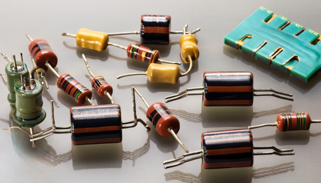
In the world of electronics and electrical engineering, three fundamental components play a pivotal role in shaping the behavior and characteristics of circuits: resistors, capacitors, and inductors. These components are the building blocks that allow engineers and designers to create intricate systems ranging from simple devices to advanced technological marvels.
Resistors are passive electronic components that exhibit a vital property called resistance, which opposes the flow of electric current. By regulating the flow of electrons, resistors are integral in controlling the voltage and current within a circuit. They find applications in voltage dividers, current limiting, signal conditioning, and various other circuit configurations.
Capacitors, on the other hand, store and release electrical energy in the form of an electric field between two conductive plates separated by an insulating material. This unique ability to store and release energy at different rates makes capacitors essential for tasks such as smoothing power supplies, filtering noise, and timing circuits. Their versatility extends to more complex functions like coupling and decoupling signals in electronic systems.
Inductors are another vital component that relies on electromagnetic properties. They are designed to store energy in a magnetic field created by a coil of wire. Inductors resist changes in current, which gives them a distinct property in circuits – they oppose rapid changes in the flow of electricity. This property makes inductors invaluable in applications involving filtering, energy storage, and creating time delays.
Understanding the characteristics, behaviors, and applications of resistors, capacitors, and inductors is fundamental for anyone seeking to delve into the realm of electronics. These components, often combined in various configurations, enable the creation of complex circuits that power everyday devices and sophisticated technologies alike. In this exploration, we will delve deeper into the individual properties and functions of these components, unraveling their contributions to the intricate world of electronics.
Types of Resistors

Resistors are essential passive components in electronics that offer resistance to the flow of electric current. They come in various types, each designed to fulfill specific requirements and functions within circuits. The different types of resistors cater to varying applications, precision levels, power handling capacities, and environmental conditions. Here are some of the most common types of resistors:
- Fixed Resistors: These are the most basic and commonly used type of resistors. They have a fixed resistance value that does not change. Fixed resistors come in various shapes and sizes, such as axial, radial, and surface mount, and they are used in a wide range of applications, from simple LED circuits to complex integrated circuits.
- Variable Resistors (Potentiometers): Also known as potentiometers or pots, these resistors have an adjustable resistance. They consist of a resistive track and a movable contact called a wiper. By changing the position of the wiper along the track, the resistance value can be adjusted. Variable resistors are often used for tasks like volume control in audio systems and setting calibration values in electronic devices.
- Thermistors: Thermistors are temperature-sensitive resistors whose resistance changes significantly with temperature variations. They can be divided into two main types: Negative Temperature Coefficient (NTC) thermistors, which have a decrease in resistance as temperature rises, and Positive Temperature Coefficient (PTC) thermistors, which exhibit an increase in resistance with temperature. Thermistors are used in temperature measurement, overcurrent protection, and temperature compensation circuits.
- Light-Dependent Resistors (LDRs): Also known as photoresistors, LDRs change their resistance based on the intensity of incident light. They are used in light-sensitive applications such as streetlight control, camera exposure control, and automatic outdoor lighting systems.
- Film Resistors: These resistors have a resistive layer deposited or printed on an insulating substrate. They offer higher precision and stability compared to carbon composition resistors. Metal film and metal oxide film resistors are two common types of film resistors, with the latter having better noise performance and higher power ratings.
- Wirewound Resistors: Wirewound resistors are constructed by winding a resistive wire around an insulating core. They offer high precision, accuracy, and power handling capabilities. Wirewound resistors are often used in applications that require precise resistance values and low temperature coefficients.
- Carbon Composition Resistors: These resistors are made by mixing carbon granules with a binder material, resulting in a composition that determines their resistance. While they are not as precise as some other types, carbon composition resistors are still used in some applications due to their ability to handle high-energy pulses and their relatively low cost.
- Surface Mount Resistors: These resistors are designed to be directly mounted onto the surface of a printed circuit board (PCB). They are compact, lightweight, and suitable for automated assembly processes, making them common in modern electronics.
Selecting the appropriate type of resistor for a given application depends on factors such as required resistance value, power handling, temperature stability, noise performance, and size constraints. The diverse range of resistor types allows engineers and designers to tailor their choices to specific circuit requirements, ultimately contributing to the functionality and performance of electronic devices and systems.
Resistance and Ohm’s Law
Resistance is a fundamental concept in electronics that characterizes how a material or component opposes the flow of electric current. It is a measure of how much a material resists the movement of electrons. The unit of resistance is the ohm (Ω), named after Georg Simon Ohm, a German physicist who formulated Ohm’s Law.
Ohm’s Law is a fundamental principle in electronics that relates three key electrical quantities: voltage (V), current (I), and resistance (R). It states that the current passing through a conductor between two points is directly proportional to the voltage across the two points and inversely proportional to the resistance between them. Mathematically, Ohm’s Law is expressed as:
V=I×R
Where:
- V represents the voltage across the resistor in volts (V).
- I is the current flowing through the resistor in amperes (A).
- R denotes the resistance of the resistor in ohms (Ω).
In practical terms, Ohm’s Law provides a simple way to understand and calculate the behavior of electrical circuits. It implies that when the voltage across a resistor increases, the current flowing through it will also increase if the resistance remains constant. Similarly, if the resistance increases while the voltage remains constant, the current will decrease.
Ohm’s Law is especially useful when working with resistors in series or parallel configurations. In series circuits, the total resistance is the sum of individual resistances, and the current remains the same across all resistors. In parallel circuits, the reciprocal of the total resistance is the sum of the reciprocals of the individual resistances, and the voltage across all resistors is the same.
Resistors find widespread application in various electronic devices and systems. They are used to limit current, divide voltage, and shape the behavior of circuits. For example, resistors are used in voltage dividers to obtain a fraction of the input voltage, in current-limiting circuits to protect components from excessive current, and in signal conditioning to shape or modify signals.
Understanding resistance and Ohm’s Law is crucial for anyone working with electronics, as it forms the foundation for comprehending how current, voltage, and resistance interact within circuits. By applying these principles, engineers and hobbyists can design, analyze, and troubleshoot electronic systems effectively, enabling the creation of innovative technologies that power our modern world.
Power Rating and Temperature Coefficient
In addition to understanding resistance and Ohm’s Law, two other important characteristics of resistors that significantly impact their performance and usage are power rating and temperature coefficient. These attributes play a crucial role in determining a resistor’s reliability, stability, and suitability for various applications.
Power Rating: The power rating of a resistor indicates the maximum amount of power it can dissipate without overheating or experiencing damage. When current flows through a resistor, some of the electrical energy is converted into heat due to the resistance. If the power dissipation exceeds the resistor’s power rating, it can lead to overheating, which might cause changes in its resistance value or even physical damage.
Resistors are manufactured with different power ratings, typically ranging from fractions of a watt to several watts or even higher. Power ratings are marked on the resistor using a code or label. It’s crucial to select a resistor with an appropriate power rating for a given application to ensure reliable operation. For example, high-power applications like power supplies and amplifiers require resistors with higher power ratings to handle the increased heat generated.
Temperature Coefficient: The temperature coefficient of a resistor measures how its resistance changes with variations in temperature. Different materials used to construct resistors exhibit different temperature coefficients. This property is denoted by the Greek letter “alpha” (α) and is usually expressed in parts per million per degree Celsius (ppm/°C).
There are two main types of temperature coefficients:
- Positive Temperature Coefficient (PTC): When a resistor has a positive temperature coefficient, its resistance increases as the temperature rises. This can be useful in applications where stability over a range of temperatures is required, such as in temperature sensors.
- Negative Temperature Coefficient (NTC): With a negative temperature coefficient, the resistance of the resistor decreases as the temperature increases. NTC resistors are often used in applications such as temperature compensation circuits and inrush current limiting, where the resistance change helps control certain behaviors within a circuit.
The temperature coefficient is an essential consideration when choosing resistors for applications that experience wide temperature variations. For instance, in precision circuits or industrial environments, using resistors with low temperature coefficients ensures that the circuit’s performance remains consistent across varying temperatures.
Power rating and temperature coefficient are critical factors to consider when selecting resistors for specific applications. Choosing the right resistor with an appropriate power rating prevents overheating and damage, while understanding the temperature coefficient allows for stable performance across temperature changes. By taking these factors into account, engineers and designers can ensure the proper functioning and reliability of electronic circuits in a wide range of scenarios.
Types of Capacitors

Capacitors are essential passive electronic components that store and release electrical energy in the form of an electric field between two conductive plates separated by an insulating material known as a dielectric. Capacitors come in various types, each tailored to specific applications based on factors such as capacitance value, voltage rating, size, and temperature stability. Here are some of the most common types of capacitors:
- Ceramic Capacitors: Ceramic capacitors are widely used due to their small size and low cost. They are constructed with a ceramic dielectric material and are available in a range of capacitance values. Ceramic capacitors are suitable for high-frequency applications, decoupling, and noise suppression. However, they can have non-linear capacitance changes with voltage and temperature variations.
- Electrolytic Capacitors: Electrolytic capacitors have a higher capacitance value compared to ceramic capacitors. They are constructed using an electrolyte and are polarized, meaning they have a positive and a negative terminal. Electrolytic capacitors are commonly used in power supply circuits and applications that require higher capacitance values. They have a voltage rating and a limited lifespan, so proper voltage orientation is crucial to prevent damage.
- Tantalum Capacitors: Tantalum capacitors are a type of electrolytic capacitor that uses tantalum as the anode material. They offer higher stability and reliability compared to aluminum electrolytic capacitors. Tantalum capacitors are often used in applications where space is limited and a higher degree of capacitance stability is required.
- Film Capacitors: Film capacitors are known for their stability, low loss, and good performance at high frequencies. They are constructed with a dielectric film between metal plates and are available in various types, including polyester, polypropylene, and polycarbonate capacitors. Film capacitors are used in applications that demand precision, such as audio systems and filtering circuits.
- Polymer Capacitors: Polymer capacitors, including conductive polymer aluminum and conductive polymer tantalum capacitors, offer improved ESR (Equivalent Series Resistance) and capacitance stability compared to traditional electrolytic capacitors. They are often used in applications where high-performance capacitors are required in a compact size.
- Super Capacitors (Supercapacitors or Ultracapacitors): Super capacitors store energy through electrostatic charge separation, offering higher energy storage compared to traditional capacitors. They have a fast charging and discharging capability, making them suitable for applications that require short bursts of energy, such as regenerative braking in hybrid vehicles and backup power systems.
- Variable Capacitors: Variable capacitors have adjustable capacitance values, typically achieved by changing the overlap area between the plates or by altering the distance between them. These capacitors are used in tuning circuits of radios, antennas, and other applications where adjustable capacitance is required.
- Mica Capacitors: Mica capacitors are known for their stability and reliability over a wide range of temperatures. They use mica as the dielectric material and are often used in high-precision applications, such as calibration standards and measurement equipment.
- Ceramic Disc Capacitors: These capacitors are compact and are often used for high-voltage applications. They have a ceramic disc with a conductive coating on each side.
- Paper and Oil Capacitors: Historically used in audio applications, these capacitors use paper impregnated with oil as the dielectric material. They provide good sound quality but can be relatively large and have limitations compared to modern capacitor types.
Choosing the right type of capacitor depends on factors such as the application’s requirements, frequency response, stability, size constraints, and environmental conditions. Each type of capacitor has its strengths and weaknesses, allowing engineers and designers to select the best-suited component for their specific circuit design and intended functionality.
Capacitance and Charge
Capacitance and charge are fundamental concepts in electronics that are closely related to the behavior and operation of capacitors, one of the essential components in electrical circuits. Understanding capacitance and charge is crucial for designing circuits, analyzing their behavior, and predicting how they respond to changes in voltage and current.
Capacitance: Capacitance is a measure of a capacitor’s ability to store electrical energy in the form of an electric field between its plates. It is defined as the ratio of the amount of charge (Q) stored on the plates of a capacitor to the potential difference (V) across the plates. Mathematically, capacitance (C) is expressed by the equation:
C=VQ
The unit of capacitance is the farad (F), named after Michael Faraday. However, farads are often quite large for practical electronic components, so capacitors are typically measured in microfarads (μF), nanofarads (nF), or picofarads (pF), depending on their capacitance values.
Capacitance is influenced by factors such as the surface area of the plates, the distance between them, and the properties of the dielectric material between the plates. A larger surface area and a closer distance between plates result in higher capacitance.
Charge: Charge refers to the accumulation of electrons (negative charge) or the absence of electrons (positive charge) on an object. In the context of capacitors, charge refers to the amount of electrons stored on the plates of the capacitor. When a voltage is applied across the capacitor, electrons are forced onto one plate, creating a negative charge, while the other plate experiences a positive charge due to the absence of electrons.
The relationship between charge (Q), capacitance (C), and voltage (V) is given by the equation:
Q=C×V
This equation illustrates that the amount of charge stored on the plates of a capacitor is directly proportional to the capacitance and the voltage applied across it. When the voltage changes, the charge stored on the capacitor also changes accordingly.
Capacitors store energy in the form of charge separation. When the voltage across a capacitor changes, the stored charge redistributes, either releasing energy back into the circuit as the voltage decreases or absorbing energy from the circuit as the voltage increases.
In summary, capacitance represents a capacitor’s ability to store charge, and charge is the accumulation of electrons on the capacitor’s plates. Together, they underpin the behavior of capacitors and play a vital role in various applications, from energy storage and smoothing voltage fluctuations to filtering signals and providing time delays in electronic circuits.
Capacitors in DC and AC Circuits
Capacitance and charge are fundamental concepts in electronics that are closely related to the behavior and operation of capacitors, one of the essential components in electrical circuits. Understanding capacitance and charge is crucial for designing circuits, analyzing their behavior, and predicting how they respond to changes in voltage and current.
Capacitance: Capacitance is a measure of a capacitor’s ability to store electrical energy in the form of an electric field between its plates. It is defined as the ratio of the amount of charge (Q) stored on the plates of a capacitor to the potential difference (V) across the plates. Mathematically, capacitance (C) is expressed by the equation:
C=VQ
The unit of capacitance is the farad (F), named after Michael Faraday. However, farads are often quite large for practical electronic components, so capacitors are typically measured in microfarads (μF), nanofarads (nF), or picofarads (pF), depending on their capacitance values.
Capacitance is influenced by factors such as the surface area of the plates, the distance between them, and the properties of the dielectric material between the plates. A larger surface area and a closer distance between plates result in higher capacitance.
Charge: Charge refers to the accumulation of electrons (negative charge) or the absence of electrons (positive charge) on an object. In the context of capacitors, charge refers to the amount of electrons stored on the plates of the capacitor. When a voltage is applied across the capacitor, electrons are forced onto one plate, creating a negative charge, while the other plate experiences a positive charge due to the absence of electrons.
The relationship between charge (Q), capacitance (C), and voltage (V) is given by the equation:
Q=C×V
This equation illustrates that the amount of charge stored on the plates of a capacitor is directly proportional to the capacitance and the voltage applied across it. When the voltage changes, the charge stored on the capacitor also changes accordingly.
Capacitors store energy in the form of charge separation. When the voltage across a capacitor changes, the stored charge redistributes, either releasing energy back into the circuit as the voltage decreases or absorbing energy from the circuit as the voltage increases.
In summary, capacitance represents a capacitor’s ability to store charge, and charge is the accumulation of electrons on the capacitor’s plates. Together, they underpin the behavior of capacitors and play a vital role in various applications, from energy storage and smoothing voltage fluctuations to filtering signals and providing time delays in electronic circuits.
Time Constants and RC Circuits
Time constants and RC (resistor-capacitor) circuits are fundamental concepts in electronics that govern the behavior of circuits involving capacitors and resistors. These concepts are essential for understanding how capacitors charge and discharge over time and how they can be used to create various electronic functions.
Time Constant: The time constant (τ) of an RC circuit is a measure of how quickly a capacitor charges or discharges through a resistor. It is calculated as the product of the resistance (R) and the capacitance (C) in the circuit:
τ=R×C
The time constant represents the time it takes for the voltage across a capacitor to reach approximately 63.2% (1 – 1/e) of its final value during charging or to decay to approximately 36.8% (1/e) of its initial value during discharging.
A shorter time constant indicates a faster response, while a longer time constant results in a slower response. Time constants are essential for determining the behavior of RC circuits in various applications, including filters, signal processing, and time-delay circuits.
RC Charging Circuit: An RC charging circuit consists of a resistor (R) and a capacitor (C) connected in series to a voltage source (usually through a switch). When the switch is closed, the capacitor starts to charge. Initially, the charging process is rapid, and the voltage across the capacitor increases exponentially. As time progresses, the rate of charging decreases, approaching its final value. The time it takes for the voltage to reach a significant portion of the source voltage is determined by the time constant τ.
The charging process follows the equation:
V(t)=Vsource×(1−e−τt)
RC Discharging Circuit: An RC discharging circuit involves a charged capacitor connected in series with a resistor. When the switch is closed, the capacitor starts to discharge through the resistor. Initially, the discharge is rapid, and the voltage across the capacitor decreases exponentially. Over time, the rate of discharge slows down, approaching zero. The time it takes for the voltage to decrease significantly is again determined by the time constant τ.
The discharging process is described by the equation:
V(t)=V0×e−τt
Applications: RC circuits find applications in various electronic devices and systems. They are used as low-pass and high-pass filters in audio circuits and communication systems, as timing components in oscillators and pulse generators, and in smoothing and delay circuits.
By adjusting the values of the resistor and capacitor in an RC circuit, engineers and designers can tailor the circuit’s response time, filtering characteristics, and time-delays to suit specific requirements. The understanding of time constants and the behavior of RC circuits is a cornerstone of electronics, enabling the creation of diverse and complex functions within electronic systems.
Inductor Construction

Inductors are passive electronic components that store energy in the form of a magnetic field created by the flow of electric current through a coil of wire. Inductors are used in a wide range of applications, from energy storage and filtering to signal processing and electromagnetic interference suppression. Understanding the construction of inductors is essential for optimizing their performance in different circuit designs.
Basic Construction: The basic construction of an inductor involves winding a wire into a coil or spiral shape. The wire is typically made of copper or another highly conductive material. The coil’s turns are closely wound to maximize the magnetic field’s strength and efficiency.
Core Material: In some inductors, a core material is used to enhance the inductance. The core material affects the inductor’s properties, such as its inductance value, saturation level, and frequency response. Different core materials are chosen based on the intended application and requirements of the circuit.
Common core materials include:
- Air Core: Inductors with no core material are called air core inductors. They have low inductance values and are often used in applications where size and weight are critical, and where core losses and saturation are not significant concerns.
- Ferromagnetic Core: Core materials like iron, ferrite, and powdered iron are commonly used to increase the inductance and improve magnetic coupling. Ferrite cores are especially popular due to their high permeability and low losses at high frequencies.
- Laminated Core: Laminated cores are constructed by layering thin sheets of a magnetic material. They are used to reduce eddy current losses that can occur in solid-core materials.
Winding Technique: The way the wire is wound around the core or form greatly affects the inductor’s characteristics. Factors like the number of turns, the spacing between turns, and the wire diameter influence the inductance value, self-resonant frequency, and other properties.
Form Factor: The physical shape of the inductor can vary depending on the application. Inductors can be found in various forms, such as axial lead inductors, surface mount chip inductors, toroidal inductors (shaped like a doughnut), and more. The form factor affects factors like self-resonance and coupling with nearby components.
Coating and Encapsulation: To protect the wire and windings from mechanical damage, moisture, and environmental factors, inductors are often coated or encapsulated with materials like epoxy or plastic. This protective layer also helps in stabilizing the inductor’s electrical characteristics.
Wire Material: High-conductivity copper wire is commonly used in inductor construction due to its excellent electrical properties. Different wire gauges (thicknesses) are chosen based on the current-carrying capacity and resistance requirements of the specific application.
By carefully selecting core materials, winding techniques, form factors, and wire properties, engineers can design inductors that meet the desired electrical performance, size constraints, and environmental considerations for a wide range of electronic applications.
Inductance and Magnetic Flux
Inductance and magnetic flux are two interconnected concepts in the realm of electronics and electromagnetism. They are fundamental to understanding the behavior of inductors, passive components that play a vital role in circuits ranging from power supplies to radio frequency circuits.
Inductance: Inductance (L) is a property of an inductor that quantifies its ability to store energy in the form of a magnetic field when current flows through it. It is the ratio of the magnetic flux (Φ) generated by the current passing through the inductor to the rate of change of the current. Mathematically, inductance is expressed by the equation:
L=dtdiΦ
Where:
- L is the inductance in henrys (H).
- Φ is the magnetic flux in webers (Wb).
- dtdi is the rate of change of current in amperes per second (A/s).
Inductance depends on factors such as the number of turns in the coil, the coil’s geometry, and the presence of a magnetic core material. The unit of inductance is the henry (H), named after Joseph Henry, an American scientist who made significant contributions to electromagnetism.
Magnetic Flux: Magnetic flux (ΦΦ) is a measure of the magnetic field passing through a surface. In the context of inductance, it refers to the magnetic field that is established around an inductor when current flows through its coil. Magnetic flux is proportional to the product of the magnetic field strength (B) and the area (A) through which the magnetic field lines pass:
Φ=B⋅A
Magnetic flux is also affected by the angle between the magnetic field lines and the normal to the surface through which they pass.
Faraday’s Law of Electromagnetic Induction: Magnetic flux is a crucial concept when discussing electromagnetic induction, which is the process by which a changing magnetic field induces an electromotive force (EMF) in a conductor. Faraday’s law of electromagnetic induction states that the EMF induced in a closed loop of wire is proportional to the rate of change of magnetic flux passing through the loop:
EMF=−dtdΦ
This law forms the basis for understanding how inductors work. When the current through an inductor changes, the magnetic flux changes, inducing a voltage (EMF) that opposes the change in current. This phenomenon gives rise to the inductor’s property of resisting changes in current flow, which is why inductors are often referred to as “self-inductors.”
Inductance and magnetic flux are critical concepts for understanding not only the behavior of inductors but also the principles of electromagnetic induction that underlie the functioning of transformers, motors, and generators. They are fundamental in the study and application of electromagnetism and electronics.
Inductors in DC and AC Circuits
Inductors are passive electronic components that store energy in the form of a magnetic field generated by the flow of electric current through a coil of wire. Inductors exhibit unique behavior in both direct current (DC) and alternating current (AC) circuits, affecting the flow of current and voltage characteristics. Understanding how inductors operate in these different circuit types is essential for designing and analyzing electronic systems.
Inductors in DC Circuits:
In DC circuits where the current is constant, the behavior of inductors is relatively straightforward. When a DC voltage is applied across an inductor, the inductor initially resists changes in current due to its property of self-inductance. This resistance leads to a transient response until the current reaches its steady-state value. Once the current becomes constant, the magnetic field around the inductor stabilizes.
At the steady state in a DC circuit, an ideal inductor acts like a short circuit, allowing current to flow unimpeded. The voltage across the inductor is zero because the rate of change of current is zero in a constant DC circuit. However, in reality, inductors have some resistance and may exhibit a small voltage drop even in a steady DC state.
Inductors in AC Circuits:
Inductors behave quite differently in alternating current (AC) circuits due to the changing nature of AC voltage. As the AC voltage alternates, the current in the inductor experiences continuous changes. The inductor’s property of opposing changes in current becomes more apparent in AC circuits.
When AC voltage is applied to an inductor, it generates a back EMF (electromotive force) due to the changing magnetic field. This back EMF opposes the change in current and causes the current to lag behind the voltage by 90 degrees in a purely inductive circuit. This lagging phase relationship is a characteristic of inductive reactance (XL), which is the opposition that an inductor offers to the flow of AC current.
Mathematically, the relationship between inductive reactance (XL), inductance (L), and frequency (f) of the AC source is given by:
XL=2πfL
In AC circuits, inductors play a crucial role in shaping the impedance (Z) of the circuit, which is the overall opposition to the flow of current. The impedance of an inductor (ZL) is equal to its inductive reactance (XL) and can be represented using the following equation:
ZL=jXL
Here, j represents the imaginary unit.
In summary, inductors exhibit distinct behaviors in DC and AC circuits due to their property of self-inductance. In DC circuits, they resist changes in current, while in AC circuits, they introduce phase shifts and opposition to changes in current flow. Understanding how inductors interact with DC and AC voltages is essential for designing circuits that efficiently utilize their characteristics and for predicting their effects on current and voltage waveforms.

RL Circuits and Time Constants
RL circuits, which consist of resistors (R) and inductors (L) connected in series or parallel configurations, are fundamental elements in electronics. They provide insights into the behavior of circuits involving both resistance and inductance. Understanding RL circuits and their associated time constants is essential for analyzing transient responses, time delays, and frequency-dependent behaviors.
Basic RL Circuit: An RL circuit consists of a resistor and an inductor connected in series or parallel. When a voltage is applied to the circuit, the inductor resists changes in current due to its self-inductance property. As a result, the current through the circuit does not change instantaneously.
Time Constant: The time constant (τ) of an RL circuit is a measure of how quickly the current in the circuit reaches its steady-state value after a change in voltage. It is calculated as the ratio of the inductance (L) to the resistance (R):
τ=RL
The time constant represents the time it takes for the current in the circuit to reach approximately 63.2% (1 – 1/e) of its final value during charging or to decrease to approximately 36.8% (1/e) of its initial value during discharging.
Charging RL Circuit: When a voltage is suddenly applied to an RL circuit, the current through the inductor increases gradually due to the inductor’s opposition to changes in current. As time progresses, the current approaches its steady-state value determined by Ohm’s Law (I=RV).
The charging process follows the equation:
I(t)=Imax×(1−e−τt)
Discharging RL Circuit: In a discharging RL circuit, where the voltage is suddenly removed, the current in the inductor decreases gradually. The inductor releases energy stored in its magnetic field.
The discharging process is described by the equation:
I(t)=Iinitial×e−τt
Applications: RL circuits are used in various applications, including delay circuits, filtering, and energy storage systems. Their behavior is particularly important in power electronics and control systems, where understanding time constants and transient responses is essential for designing circuits that respond predictably to changes in input signals.
By manipulating resistance, inductance, and time constants, engineers can create circuits with desired behaviors, such as smoothing voltage fluctuations, creating time delays, and implementing complex signal processing operations. Understanding the interplay between resistance, inductance, and time constants is fundamental for effectively utilizing RL circuits in electronic designs.
Conclusion
Resistors, capacitors, and inductors are fundamental passive electronic components that play crucial roles in shaping the behavior of electrical circuits. Each of these components contributes unique properties to the circuits they are integrated into, enabling a wide range of applications across various fields.
Resistors serve as passive elements that impede the flow of current in a circuit. They are essential for controlling current levels, voltage division, and setting bias points in transistors. The ability to accurately calculate and select resistance values is central to designing circuits with desired characteristics. From fixed resistors to variable ones like potentiometers, they find applications in voltage regulation, signal conditioning, and current limiting.
Capacitors are adept at storing and releasing electrical energy, and they influence circuit behavior by creating time-dependent responses. Capacitance allows them to act as energy storage devices, filtering elements, and timing components. Their role in smoothing out power supplies, coupling audio signals, and generating time delays makes them indispensable in a variety of electronic applications.
Inductors exhibit a distinct property of opposing changes in current, which leads to the generation of electromagnetic fields. This property forms the basis for their applications in transformers, where they facilitate energy transfer, and in inductive loads such as motors and solenoids, where their magnetic fields create mechanical movement. In circuits, inductors contribute to the behavior of RL circuits, creating time-dependent responses and impedance effects.
Collectively, these components interact and complement each other in countless electronic designs. Their ability to store energy, limit current, shape voltage waveforms, and produce electromagnetic fields allows engineers and designers to create intricate circuits that perform complex functions. Understanding the characteristics and behaviors of resistors, capacitors, and inductors empowers engineers to harness their potential for applications ranging from power electronics to signal processing, communication systems, and beyond. In the ever-evolving landscape of technology, these foundational components continue to be indispensable building blocks for innovations across industries.