Voltage dividers and potentiometers are fundamental electrical components used in a wide range of applications to control, measure, and distribute electrical voltage. These components play a crucial role in electronics and circuitry, enabling the manipulation of voltage levels and the adjustment of parameters like brightness, volume, and sensor sensitivity. Understanding the principles behind voltage dividers and potentiometers is essential for anyone delving into electronics, engineering, or any field that involves electrical circuits.
A voltage divider is a simple circuit arrangement that divides a voltage into smaller fractions using resistors. It consists of two or more resistors connected in series across a voltage source. The output voltage is taken from the connection between these resistors. Voltage dividers find applications in various scenarios, such as creating reference voltages, biasing transistors, and sensing analog signals. They are often employed to interface between different parts of a circuit that require different voltage levels.
Potentiometers, often referred to as “pots,” are variable resistors with an adjustable tapping point. They allow precise control of the output voltage or signal in a circuit. Potentiometers consist of a resistive element with three terminals: two fixed end terminals and a wiper that moves along the resistive track. By adjusting the wiper’s position, the effective resistance between the wiper and either end terminal changes, thus altering the voltage division ratio. Potentiometers are widely used for volume control in audio devices, setting the contrast in displays, and fine-tuning various parameters in electronic circuits.
This introduction will delve deeper into the principles governing voltage dividers and potentiometers, their mathematical relationships, practical applications, and considerations for using them effectively in different circuits. Whether you’re a hobbyist, a student, or a professional in the field of electronics, gaining a solid grasp of voltage dividers and potentiometers is essential for harnessing the power of electrical circuits and systems.
Basic Voltage Divider Circuit
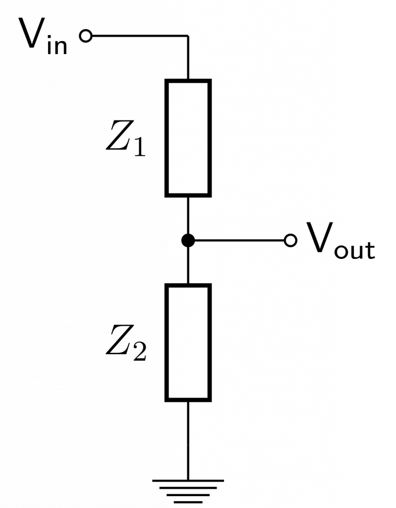
A basic voltage divider circuit is a straightforward arrangement of resistors used to divide a voltage into smaller fractions. It’s a fundamental circuit concept that finds applications in various electronics and electrical engineering scenarios. The circuit comprises two or more resistors connected in series across a voltage source, with the output voltage taken from the junction between these resistors.
Components of a Basic Voltage Divider Circuit:
- Voltage Source (V_in): This is the source of the initial voltage that needs to be divided. It can be a battery, power supply, or any other source of electrical potential.
- Resistors (R1 and R2): The key components of the voltage divider are the resistors. R1 is connected to the positive terminal of the voltage source, and R2 is connected to the negative terminal. These resistors determine the division ratio and the resulting output voltage.
- Output Terminal (V_out): The output voltage is measured across the connection point between R1 and R2. This is the voltage that’s been divided and is available for use in the circuit.
Voltage Division Principle:
The voltage across each resistor in a series circuit is directly proportional to its resistance. According to Ohm’s law (V = I * R), the voltage drop across a resistor is equal to the current flowing through it multiplied by its resistance. In a voltage divider circuit, the current flowing through both resistors is the same, as they are connected in series. Therefore, the voltage across each resistor is directly proportional to its resistance.
Mathematical Relationship:
The relationship between the input voltage (V_in), the resistances of R1 and R2, and the output voltage (V_out) can be expressed as follows:
V_out = V_in * (R2 / (R1 + R2))
This equation reveals that the output voltage is a fraction of the input voltage, determined by the ratio of R2 to the sum of R1 and R2. By appropriately choosing the values of R1 and R2, you can obtain the desired output voltage level.
Applications:
Voltage divider circuits have numerous applications, including:
- Creating Reference Voltages: Voltage dividers can generate reference voltages for comparison or measurement purposes in various circuits.
- Sensor Interface: Voltage dividers are used to interface sensors that provide analog signals (like temperature sensors or light sensors) with microcontrollers or other digital circuits.
- Biasing Transistors: In transistor biasing, voltage dividers set the appropriate base voltage to ensure proper transistor operation.
- Analog-to-Digital Conversion: Voltage dividers can be part of voltage scaling circuits used in analog-to-digital converters (ADCs).
Considerations:
- Load Impedance: The output of a voltage divider circuit can be affected by the load connected to it. A high load impedance is desired to minimize this effect.
- Tolerance: The resistors used should have tolerances that are suitable for the desired accuracy of the output voltage.
- Current Draw: Keep in mind that voltage dividers consume some current from the source. If the current drawn is significant, it might affect the overall circuit behavior.
A basic voltage divider circuit is a building block for more complex circuits and systems. Its simplicity and versatility make it an essential concept to understand in the realm of electronics and circuit design.
Voltage Divider Rule
The Voltage Divider Rule, also known as the Voltage Division Rule, is a fundamental principle in electronics that provides a method for calculating the voltage across a specific resistor or component in a series circuit. This rule is particularly useful in voltage divider circuits, where a series of resistors is connected in series across a voltage source, and you want to determine the voltage drop across one of those resistors.
Explanation of the Voltage Divider Rule:
In a series circuit, where components are connected one after another in a single path, the current remains constant throughout. However, the voltage across each component is not necessarily the same due to the presence of resistors. The Voltage Divider Rule states that the voltage across a specific resistor in a series circuit is proportional to its resistance compared to the total resistance of the circuit.
Mathematically, the rule can be expressed as:
V_x = V_in * (R_x / R_total)
Where:
- V_x: Voltage across the specific resistor or component of interest.
- V_in: Input voltage or the voltage across the entire series circuit.
- R_x: Resistance of the specific resistor or component of interest.
- R_total: Total resistance of the series circuit, which is the sum of all individual resistances.
Application of the Voltage Divider Rule:
The Voltage Divider Rule finds widespread use in various applications, such as:
- Sensor Interfacing: When working with sensors that provide analog outputs (like temperature sensors or light sensors), the Voltage Divider Rule helps determine the output voltage that corresponds to a specific physical parameter.
- Reference Voltage Generation: Voltage dividers are often used to create reference voltage levels for comparison in circuits like operational amplifier configurations.
- Biasing Circuits: In transistor biasing, the Voltage Divider Rule helps establish the correct bias voltage to ensure proper transistor operation.
- Potentiometer Output: In potentiometers, the rule helps calculate the output voltage based on the wiper position and the potentiometer’s resistance values.
Limitations and Considerations:
- The Voltage Divider Rule assumes that the current flowing through all resistors is the same, as they are connected in series. This is valid when the current drawn by the load connected to the output is much higher than the current flowing through the divider resistors.
- The rule is most accurate when the load impedance (resistance) connected to the output is significantly larger than the resistance of the resistors in the voltage divider circuit. If the load impedance is not much greater, it will affect the accuracy of the calculated voltage.
Voltage Divider with Multiple Taps
A Voltage Divider with Multiple Taps, often referred to as a “multi-tap voltage divider” or a “potentiometer array,” is an extension of the basic voltage divider concept. It involves using multiple resistors with different tapping points to create various output voltage levels based on the position of the taps. This arrangement offers greater flexibility and versatility in generating different reference voltages or signal levels within a circuit.
Construction and Components:
A multi-tap voltage divider consists of several resistors connected in series. Unlike a simple voltage divider with just two resistors, a multi-tap version includes additional tapping points along the resistor network. These tapping points can be connected to different points of the circuit to create distinct output voltage levels.
Applications:
1. Variable Voltage Output: One of the primary applications of a multi-tap voltage divider is to provide variable voltage output. By selecting different tapping points, you can adjust the output voltage according to the specific requirements of the circuit. This functionality is commonly used in applications such as volume controls in audio equipment or brightness controls in displays.
2. Calibration and Testing: In test and measurement applications, multi-tap voltage dividers are used to generate known reference voltages for calibration purposes. By selecting specific taps, you can simulate different voltage conditions to verify the accuracy and performance of electronic devices.
3. Signal Conditioning: Multi-tap voltage dividers are also used in signal conditioning circuits. They can help scale and adjust analog signals from sensors to match the input requirements of subsequent circuit stages, such as analog-to-digital converters (ADCs).
4. Biasing and Level Shifting: In electronic circuits that require biasing or level shifting, multi-tap voltage dividers offer a practical way to set the correct bias voltages or shift signal levels as needed for proper operation.
5. Voltage Reference Networks: Multi-tap voltage dividers are used to create precise voltage reference networks for applications like analog signal processing and analog-to-digital conversion.
Considerations:
- Resistor Values: The choice of resistor values determines the resolution and step size of the available output voltage levels. Proper selection is crucial to ensure that the required output voltages can be accurately achieved.
- Tolerance and Accuracy: The accuracy of the output voltage levels depends on the tolerance of the resistors used. Lower-tolerance resistors are preferable for applications demanding high precision.
- Load Impedance: As with any voltage divider, the load impedance connected to the tapping points can affect the accuracy of the output voltage. The load impedance should be significantly larger than the resistance of the resistors in the divider network.
- Tapping Mechanism: The mechanism used to select different tapping points should be reliable and durable. In some cases, mechanical switches or digital control methods are employed to change the tap position.
Basic Potentiometer Structure

The basic potentiometer, often referred to as a “pot,” is a simple yet essential electronic component used for adjusting and varying voltage levels in circuits. It is a type of variable resistor with three terminals and an adjustable tapping point. Potentiometers come in various shapes, sizes, and configurations, but they all share a fundamental structure.
Components of a Basic Potentiometer Structure:
- Rotating Shaft: The potentiometer consists of a shaft that can be rotated. This shaft is often attached to a knob or some external control mechanism that allows the user to adjust the position of the tapping point.
- Resistive Element: The heart of the potentiometer is the resistive element. This is a strip or track of resistive material, typically made of carbon or conductive plastic, wound or printed onto an insulating substrate. It extends from one end of the potentiometer to the other.
- Wiper: The wiper is a moveable contact that slides along the resistive element when the shaft is rotated. It’s typically a small metallic or conductive element connected to the potentiometer’s rotating shaft. The position of the wiper along the resistive element determines the effective resistance between the wiper terminal and the other two terminals.
- Terminals: Potentiometers have three terminals: the two fixed end terminals and the wiper terminal. One end terminal is connected to the beginning of the resistive element, the other end terminal is connected to the opposite end of the resistive element, and the wiper terminal is connected to the wiper.
How It Works:
As the potentiometer’s shaft is rotated, the wiper moves along the resistive element, changing the point of contact. This changes the portion of the resistive element through which current flows. The resistance between the wiper terminal and the end terminals varies accordingly, creating a voltage divider effect.
Applications:
Basic potentiometers are used in a wide range of applications, including:
- Volume Control: In audio systems, potentiometers are used to control the volume by adjusting the voltage level sent to the amplifier.
- Brightness Control: In displays and lighting systems, potentiometers can adjust the brightness or intensity of the output.
- Analog Signal Adjustment: Potentiometers are employed to fine-tune analog signals in various stages of electronics, like amplifiers or filters.
- Sensor Calibration: Potentiometers can calibrate sensors by adjusting the voltage levels they provide as outputs.
- Setting Bias Voltages: In electronics, they can set bias voltages for transistors or operational amplifiers to ensure proper operating conditions.
Considerations:
- Resistance Value: Potentiometers come in various resistance values. Choosing the appropriate value depends on the application’s requirements.
- Taper: Potentiometers can have different taper profiles (linear, logarithmic, or exponential). The taper affects how the resistance changes with the rotation of the shaft.
- Tolerance: Tolerance specifies the allowable variation in the actual resistance compared to the labeled resistance value.
- Mechanical Durability: The quality of the potentiometer’s construction influences its mechanical lifespan and reliability.
Basic potentiometers serve as versatile tools for adjusting voltage levels and tuning analog signals in electronic circuits. Their simple yet effective design has made them indispensable components in various electronic devices and systems.
Potentiometer Applications
Potentiometers, or pots, are versatile components with a wide range of applications in electronics and various industries. Their ability to provide variable resistance and adjust voltage levels makes them valuable tools for controlling and tuning circuits. Here are some common potentiometer applications:
1. Volume Control: Perhaps one of the most recognizable uses of potentiometers is in audio equipment for volume control. Potentiometers allow users to adjust the level of audio output from devices like speakers, headphones, amplifiers, and radios.
2. Brightness and Contrast Adjustment: Potentiometers are used to adjust the brightness and contrast levels in displays, including LCD monitors, televisions, and electronic screens. These controls provide the user with the ability to optimize the visual experience.
3. Tuning and Calibration: Potentiometers play a crucial role in tuning and calibrating devices and sensors. For example, in radio tuning circuits, potentiometers help select the desired frequency. In sensor applications, they assist in calibrating the sensor’s output to match a specific parameter.
4. Analog Signal Adjustment: Potentiometers are used in analog signal processing circuits, such as amplifiers, filters, and equalizers. They allow engineers and technicians to fine-tune signal levels and tailor the circuit’s behavior.
5. Biasing Circuits: In electronic circuits involving transistors or operational amplifiers, potentiometers are used to set bias voltages or reference levels. Proper biasing is essential for ensuring optimal device performance.
6. Voltage Regulation: Potentiometers can be used as variable resistors in voltage regulator circuits. They provide a way to adjust the output voltage within certain limits, making them useful in power supply designs.
7. Test and Measurement: Potentiometers are used in test and measurement equipment to simulate different resistance values, voltage levels, or load conditions for testing devices’ responses under various conditions.
8. User Interface Controls: Potentiometers are often integrated into user interface controls for various devices. They are used in rotary knobs, sliders, and touch-sensitive controls to provide users with a tactile and adjustable interaction with devices.
9. Offset and Gain Adjustment: In instrumentation circuits, potentiometers can be used to adjust the offset and gain of sensor outputs, ensuring accurate measurements and readings.
10. Servo Control: Potentiometers are employed in servo control systems to provide feedback on the position of mechanical components. This feedback helps maintain the desired position and control the movement of motors and actuators.
11. Light Dimming: In lighting applications, potentiometers are used to dim lights by adjusting the voltage supplied to them. This feature is commonly found in architectural lighting, stage lighting, and residential lighting.
12. Thermostats and HVAC Systems: Potentiometers are used in thermostats and heating, ventilation, and air conditioning (HVAC) systems to control temperature settings and adjust the system’s operation.
13. Robotics and Automation: In robotics and automation, potentiometers can be used to determine the position of robotic arms, actuators, and other moving components.
14. Musical Instruments: Musical instruments like guitars and keyboards use potentiometers to control parameters such as tone, modulation, and effect levels.
These are just a few examples of the many applications of potentiometers. Their versatility and adaptability make them essential components in various industries, enabling precise control, adjustment, and customization of electronic systems and devices.
Voltage Divider using Potentiometers
A voltage divider using potentiometers combines the principles of both voltage dividers and potentiometers to create a circuit that allows adjustable voltage division. This setup is particularly useful when you want to create a variable reference voltage or when you need to divide a voltage by a ratio that can be changed dynamically. Here’s how it works:
Construction and Components:
A voltage divider using potentiometers involves using one or more potentiometers in a circuit. Each potentiometer has three terminals: the two fixed end terminals and the wiper terminal. The fixed terminals are connected to a voltage source, typically the positive and negative terminals. The wiper terminal is connected to the circuit where you want to obtain a variable voltage output.
Operation:
As the potentiometer’s shaft is rotated, the wiper moves along the resistive element. This changes the resistance between the wiper terminal and the other two terminals. Since the wiper terminal is connected to the circuit of interest, the resistance between the wiper terminal and the fixed end terminal determines the voltage that will be dropped across the wiper terminal.
Applications:
- Variable Voltage Output: The primary application of a voltage divider using potentiometers is to provide a variable voltage output. By adjusting the potentiometer’s wiper position, you can change the output voltage according to your requirements. This functionality is useful in scenarios like volume control, light dimming, or tuning analog signals.
- Calibration: When you need to calibrate a system by providing a range of reference voltages, a voltage divider using potentiometers becomes handy. By adjusting the potentiometer, you can simulate different conditions for testing and calibration purposes.
- Sensor Interface: In cases where you want to interface a sensor with an analog output to a microcontroller or other digital circuit, you can use a voltage divider using a potentiometer. This setup allows you to adjust the sensor’s output voltage range to match the input range of the digital circuit.
- Biasing Circuits: Potentiometers in voltage dividers can be used to set bias voltages for transistors, operational amplifiers, or other components in biasing circuits.
Considerations:
- Potentiometer Taper: Depending on the application, you might choose a potentiometer with a linear, logarithmic, or exponential taper to suit the desired behavior of the voltage division.
- Load Impedance: The load impedance connected to the output of the voltage divider should be much larger than the resistance of the potentiometer to minimize loading effects.
- Resolution and Accuracy: The resolution of the adjustable voltage output depends on the quality and precision of the potentiometer used. Lower tolerance and higher-quality potentiometers provide better accuracy.
- Mechanical Durability: The mechanical durability of the potentiometer is essential, especially if the device will be frequently adjusted.
A voltage divider using potentiometers offers a practical way to create an adjustable voltage output within a circuit. This configuration provides engineers and hobbyists with a convenient method to fine-tune and tailor voltage levels to match specific requirements in various applications.
Linear vs. Logarithmic Potentiometers
Linear and logarithmic (log) potentiometers are two common types of potentiometers with distinct taper characteristics. These characteristics determine how the resistance of the potentiometer changes as the wiper position is adjusted. Each type has its own advantages and applications based on the specific behavior they exhibit.
Linear Potentiometers:
Taper: Linear potentiometers have a linear taper, meaning the change in resistance is directly proportional to the change in wiper position. As you rotate the potentiometer’s shaft, the resistance changes uniformly, resulting in a linear change in the output voltage.
Applications:
- Volume Controls: Linear potentiometers are often used for volume control in audio devices. This is because our perception of loudness is approximately linear with the input signal amplitude, making a linear taper suitable for adjusting audio volume levels.
- Brightness Controls: In displays and lighting systems, linear potentiometers can be used to control brightness levels, as our perception of brightness typically aligns with linear changes in intensity.
- Analog Signal Adjustments: Linear potentiometers are suitable for applications where a direct correlation between wiper position and resistance change is desired, such as in amplifier gain adjustment or analog signal scaling.
Logarithmic Potentiometers:
Taper: Logarithmic potentiometers have a logarithmic taper, also known as an audio taper. In this case, the change in resistance is logarithmically proportional to the change in wiper position. This means that the resistance changes more significantly at one end of the potentiometer’s rotation and less significantly at the other.
Applications:
- Tone Controls: Logarithmic potentiometers are commonly used in tone control circuits, where our perception of treble and bass levels corresponds to logarithmic changes in frequency response.
- Exponential Processes: Logarithmic potentiometers are suitable for applications that involve exponential processes, such as adjusting the gain of an audio amplifier to match the logarithmic nature of our hearing perception.
- Decibel Controls: In audio systems, where sound levels are often measured in decibels (dB), logarithmic potentiometers are appropriate for controlling sound intensity levels due to their logarithmic response.
Choosing Between Linear and Logarithmic Potentiometers:
Choosing between linear and logarithmic potentiometers depends on the specific application and the user’s perception of the controlled parameter. Linear potentiometers are more suitable for scenarios where a direct and even change in resistance corresponds to the desired behavior, such as linear changes in volume or brightness. Logarithmic potentiometers are ideal for applications that align with our perception of sound or other quantities that change logarithmically, like decibels.
Ultimately, the choice between linear and logarithmic potentiometers should be made based on the desired user experience, the function being controlled, and the relationship between wiper position and the controlled parameter.
Potentiometer vs. Digital Controls
Potentiometers and digital controls are two distinct methods for adjusting and controlling various parameters in electronic circuits and systems. Each approach offers its own advantages and drawbacks, making them suitable for different applications. Here’s a comparison of potentiometers and digital controls:
Potentiometers:
Advantages:
- Simplicity: Potentiometers are simple and intuitive to use. They involve a physical knob or slider that can be easily adjusted by hand.
- Real-time Adjustment: Potentiometers provide real-time adjustment. As you turn the knob or move the slider, the parameter being controlled changes immediately.
- Analog Feel: Potentiometers offer an analog feel to the control process, allowing for smooth and continuous adjustments.
- Physical Feedback: Users get physical feedback through the tactile sensation of turning the knob or sliding the control.
- Cost-Effective: Potentiometers are generally cost-effective and don’t require complex digital interfaces.
Drawbacks:
- Wear and Tear: Mechanical potentiometers can wear out over time due to physical movement, resulting in reduced accuracy and potential signal noise.
- Limited Precision: The precision of potentiometers is limited by factors like their resistance tolerance and mechanical wear.
- Calibration: Calibration can be challenging, and potentiometers might require periodic recalibration.
Digital Controls:
Advantages:
- High Precision: Digital controls can offer high precision and accuracy, especially when using digital encoders or microcontrollers.
- Programmability: Digital controls can be programmed to provide specific output levels, allowing for fine-tuned and consistent adjustments.
- Remote Control: Digital controls can be operated remotely through digital interfaces, making them suitable for applications where physical access is limited.
- Memory and Presets: Digital controls can store presets and memory settings for different configurations.
- Automation: Digital controls are well-suited for automation and integration into complex systems.
Drawbacks:
- Complexity: Digital controls can be more complex to implement than potentiometers, involving microcontrollers, digital interfaces, and software programming.
- Latency: In some cases, there might be a delay between adjusting the control and observing the change in the controlled parameter due to processing and communication delays.
- Lack of Tactile Feedback: Digital controls might lack the tactile feedback that potentiometers provide, making them less intuitive for some users.
Choosing Between Potentiometers and Digital Controls:
The choice between potentiometers and digital controls depends on the specific requirements of the application:
- If real-time analog adjustment, simplicity, and a tactile experience are important, potentiometers might be preferable.
- If high precision, programmability, remote operation, and integration into digital systems are required, digital controls could be the better choice.
Often, a combination of both approaches can be used, where a digital control interface adjusts analog components like potentiometers in the background. This hybrid approach balances the advantages of both methods while addressing their drawbacks.
Conclusion
Voltage dividers and potentiometers are fundamental components in the world of electronics, each serving unique purposes in various applications. Voltage dividers provide a simple yet effective means to divide voltages and create reference levels within circuits. They find use in biasing transistors, sensing analog signals, and establishing voltage references for different components. By understanding the principles behind voltage dividers, engineers and enthusiasts gain the ability to manipulate voltage levels and tailor them to specific needs.
Potentiometers, on the other hand, offer a dynamic way to adjust and control voltages within a circuit. With their adjustable tapping points and variable resistance, potentiometers allow for real-time tuning of parameters such as volume, brightness, and signal levels. Their applications span from user interface controls and audio systems to precise calibration and sensor interfacing. Recognizing the differences between linear and logarithmic potentiometers further enhances the ability to create circuits that match the intended user experience and perception.
Combining the concepts of voltage dividers and potentiometers leads to the creation of flexible circuits where adjustable voltage division meets dynamic control. This synergy enables the design of systems that cater to individual preferences, adapt to changing conditions, and integrate seamlessly into larger electronic setups. Whether designing circuits for audio equipment, control systems, or instrumentation, a solid grasp of voltage dividers and potentiometers is a valuable asset in harnessing the potential of electronics to its fullest. These foundational concepts lay the groundwork for innovation and problem-solving across diverse domains, making them essential knowledge for anyone venturing into the world of electronics and electrical engineering.