Diodes and rectifiers are fundamental electronic components that play a crucial role in modern electronics and power systems. These devices are designed to control the flow of electric current in a specific direction, enabling the conversion of alternating current (AC) to direct current (DC) and serving as essential building blocks in various electronic circuits.
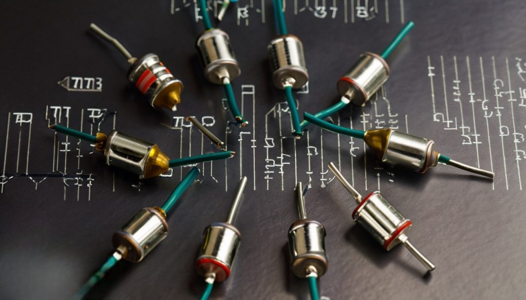
A diode is a two-terminal semiconductor device that allows current to flow in only one direction. It acts as a valve for electric current, permitting it to pass from the anode to the cathode while effectively blocking reverse current flow. This asymmetric behavior gives rise to a range of applications, from converting AC to DC to protecting circuits from voltage spikes and serving as key components in signal demodulation and voltage regulation.
Rectifiers, on the other hand, are circuits or devices built using diodes to convert AC into DC. They come in several configurations, including half-wave rectifiers, full-wave rectifiers, and bridge rectifiers. These rectification processes are crucial in power supplies for electronic devices, ensuring a steady and usable DC voltage is supplied to the components.
In this exploration of diodes and rectifiers, we will delve into their operating principles, various types, applications in electronics and power systems, and the significance they hold in shaping the way we harness and utilize electrical energy. Whether in everyday consumer electronics or large-scale industrial systems, diodes and rectifiers continue to be essential components that facilitate the modern technological landscape.
Diode Operation and Characteristics
A diode is a semiconductor device with two terminals, the anode and the cathode, that exhibits a unique behavior in regulating the flow of electric current. Its fundamental principle lies in the creation of a junction between two types of semiconductor materials – typically p-type and n-type – which gives rise to its distinctive properties.
Diode Junction and Biasing: At the heart of a diode’s operation is the p-n junction, where the p-type material (which has an excess of positively charged carriers or “holes”) meets the n-type material (which has an excess of negatively charged carriers or electrons). This junction forms a barrier called the depletion region, characterized by the absence of majority carriers. When a diode is in its unbiased state (no external voltage applied), this depletion region acts as a barrier preventing significant current flow.
Forward Bias: When a positive voltage is applied to the anode (p-side) with respect to the cathode (n-side), it reduces the width of the depletion region. This process, known as forward biasing, allows majority carriers (holes in the p-side and electrons in the n-side) to move towards the junction. As a result, the diode becomes conductive, enabling current to flow easily from the anode to the cathode. The voltage required to overcome the potential barrier and establish this flow is called the forward voltage or the diode’s voltage drop.
Reverse Bias: Applying a negative voltage to the anode with respect to the cathode widens the depletion region, creating a higher potential barrier. This is called reverse biasing and effectively blocks the flow of majority carriers across the junction. While a small leakage current may still occur due to minority carriers, it is generally very low compared to the current in forward bias.
Ideal vs. Real Diode: In an ideal diode, there is an instantaneous transition between complete conduction (in forward bias) and complete blocking (in reverse bias). However, real-world diodes exhibit a gradual transition region known as the “knee” in their current-voltage characteristic curve. This curve illustrates the relationship between the voltage across the diode and the current flowing through it.
Diode Characteristics: Several key characteristics define the behavior of diodes:
- Forward Voltage Drop (Vf): The voltage required to enable significant forward current flow.
- Reverse Breakdown Voltage (VBR): The voltage at which the diode experiences a sudden increase in reverse current, possibly leading to its destruction. This phenomenon is called reverse breakdown, and there are two types: Zener breakdown (intentional) and avalanche breakdown (unintentional).
- Maximum Forward Current (If): The maximum allowable forward current without damaging the diode.
- Reverse Current (IR): The small leakage current that flows in reverse bias.
- Diode Capacitance: In reverse bias, the p-n junction behaves like a capacitor, which affects high-frequency applications.
- Temperature Dependence: Diode characteristics, particularly the forward voltage drop, can change with temperature.
Understanding diode operation and characteristics is essential for designing and analyzing electronic circuits involving diodes. From rectification and voltage regulation to signal modulation and protection against voltage spikes, diodes’ distinct behavior serves as a cornerstone in modern electronics.
Applications of Diodes
Diodes, with their ability to control the flow of electric current in a unidirectional manner, find a wide range of applications in various fields of electronics and technology. Their unique behavior makes them indispensable for tasks ranging from rectification and signal modulation to protection and voltage regulation. Here are some of the key applications of diodes:
1. Rectification: Diodes are extensively used in rectifier circuits to convert alternating current (AC) into direct current (DC). Half-wave rectifiers, full-wave rectifiers, and bridge rectifiers employ diodes to allow current to flow in only one direction, smoothing out the AC waveform and producing a steady DC output.
2. Voltage Regulation: Zener diodes are designed to operate in reverse breakdown, maintaining a nearly constant voltage across them. They are used in voltage regulation circuits, protecting sensitive components from voltage fluctuations by maintaining a stable reference voltage.
3. Signal Demodulation: Diodes play a crucial role in demodulating signals in communication systems. In amplitude modulation (AM) radio receivers, for example, diodes are used to extract the original audio signal from the carrier wave.
4. Protection against Voltage Spikes: Transient voltage suppressor (TVS) diodes, also known as surge suppressor diodes or transient voltage clamping diodes, are used to protect electronic devices from voltage spikes caused by events such as lightning strikes and electrostatic discharge (ESD).
5. Light Emitting Diodes (LEDs): LEDs are a type of diode that emits light when current flows through them. They are used in a wide range of applications, including indicator lights, displays, backlighting for screens, automotive lighting, and general illumination due to their efficiency and long life.
6. Laser Diodes: Laser diodes are specialized diodes that emit coherent light when current passes through them. They are essential components in various applications, including telecommunications, medical devices, barcode scanners, laser pointers, and even in cutting and welding tools.
7. Power Diodes: Power diodes, designed to handle high currents and voltages, are used in power electronics applications such as voltage rectification in power supplies, motor drive circuits, and welding equipment.
8. Clipping and Clamping Circuits: Diodes are used in clipping circuits to limit the amplitude of a signal. In clamping circuits, they shift the DC level of a waveform, which can be useful in audio and video applications.
9. Logic Gates: Diodes are key components in logic gates, which are the building blocks of digital circuits. They are used to create OR, AND, NOT, and other logical operations.
10. Photodiodes and Solar Cells: Photodiodes convert light into current and are used in light detection applications like photodetectors, cameras, and solar cells. Solar cells, also known as photovoltaic cells, convert sunlight into electricity and are used to harness solar energy.
11. Varactor Diodes: Varactor diodes, also called varicap diodes, are used as voltage-controlled capacitors in tuning circuits of radio and television receivers, voltage-controlled oscillators, and phase-locked loops.
12. Microwave and RF Applications: Schottky diodes and tunnel diodes find applications in high-frequency circuits, microwave detectors, mixers, and frequency multipliers due to their fast switching and low noise characteristics.
Introduction to Rectifiers
Rectifiers are essential electronic circuits or devices designed to convert alternating current (AC) into direct current (DC). In many electronic systems and devices, a stable source of direct current is required for proper operation. This is where rectifiers come into play, as they enable the conversion of the constantly changing direction of current in AC into a unidirectional flow in DC.
Purpose of Rectification: The primary purpose of rectification is to provide a reliable and consistent source of power for various electronic components and systems. Many electronic devices, from small gadgets to large industrial equipment, rely on direct current for their operation. By converting AC to DC, rectifiers ensure that these devices receive the appropriate and controlled power supply.
Types of Rectifiers: There are several types of rectifiers, each with its own characteristics and applications:
- Half-Wave Rectifiers: These rectifiers use a single diode to allow only half of the AC waveform to pass, effectively cutting off the negative portion. While simple, they are not very efficient due to the significant loss of power in the unused half of the waveform.
- Full-Wave Rectifiers: Full-wave rectifiers use a configuration of diodes to allow both halves of the AC waveform to be converted into DC. This results in higher efficiency compared to half-wave rectifiers.
- Bridge Rectifiers: A bridge rectifier is a specific type of full-wave rectifier that uses four diodes arranged in a bridge configuration. This design allows for more efficient conversion of AC to DC, eliminating the need for a center-tapped transformer often used in full-wave rectifiers.
- Center-Tapped Rectifiers: These are another form of full-wave rectifiers that use a center-tapped transformer to split the AC waveform into two halves. They are less efficient and less common due to the availability of more efficient bridge rectifiers.
Rectification Process: In a rectifier circuit, diodes play a crucial role by allowing current to flow in one direction while blocking it in the opposite direction. During the positive half-cycle of the AC voltage, the diode becomes forward-biased, allowing current to flow through it. During the negative half-cycle, the diode becomes reverse-biased, effectively blocking the current.
Ripple and Filtering: One challenge in rectification is the presence of a residual AC component, often referred to as ripple, in the output DC voltage. This ripple can be reduced using filtering techniques, such as capacitors, which store energy during the peaks of the rectified waveform and release it during the troughs, smoothing out the voltage.
Applications: Rectifiers are used in a wide array of applications, including:
- Power supplies for electronic devices and equipment.
- Battery charging systems.
- Welding machines.
- Motor drive circuits.
- Electroplating and electrochemical processes.
- Uninterruptible power supplies (UPS).
- Converters for renewable energy sources like solar panels and wind turbines.
Rectifiers are crucial components that facilitate the conversion of alternating current into direct current, enabling a steady and reliable power source for a wide range of electronic devices and systems. The choice of rectifier type depends on factors such as efficiency, voltage requirements, and application specifics.
Types of Rectifiers
Rectifiers are electronic circuits used to convert alternating current (AC) into direct current (DC). They are essential for providing a stable and consistent source of power to various electronic devices and systems. There are different types of rectifiers, each with its own configuration and characteristics. Here, we’ll explore the most common types of rectifiers:
1. Half-Wave Rectifier: The half-wave rectifier uses a single diode to allow only one half of the AC waveform to pass through, effectively cutting off the negative portion of the waveform. While simple in design, half-wave rectifiers are not very efficient as they waste a significant portion of the input power. They are typically used in applications where efficiency is not a primary concern.
2. Full-Wave Rectifier: Full-wave rectifiers are more efficient than half-wave rectifiers. They come in two configurations: center-tapped and bridge rectifiers.
- Center-Tapped Full-Wave Rectifier: This configuration uses a center-tapped transformer to split the AC waveform into two halves. Two diodes are used to rectify each half of the waveform. This type of rectifier is relatively simple but less efficient due to the presence of the center-tapped transformer.
- Bridge Rectifier: The bridge rectifier is a more efficient design that uses four diodes arranged in a bridge configuration. It can convert both halves of the AC waveform into DC, eliminating the need for a center-tapped transformer. Bridge rectifiers are widely used in various applications due to their higher efficiency and simpler construction.
3. Bridge Rectifier with Capacitor Filter: To reduce the ripple in the output DC voltage, capacitors can be added after the bridge rectifier. These capacitors store energy during the peaks of the rectified waveform and release it during the troughs, smoothing out the voltage. This type of rectifier is commonly used in power supply applications where a more stable DC output is required.
4. Bridge Rectifier with Capacitor and Inductor Filters (LC Filter): For applications demanding even lower ripple and better filtering, an LC filter can be added in conjunction with the bridge rectifier and capacitor. The inductor smooths out the voltage variations further, resulting in a cleaner DC output. This configuration is often used in sensitive electronics and audio equipment.
5. Voltage Doubler Rectifier: A voltage doubler rectifier uses a combination of diodes and capacitors to double the DC output voltage. This is achieved by utilizing the charging and discharging characteristics of capacitors. Voltage doubler rectifiers are used in applications where a higher DC voltage is required without using a higher AC input voltage.
6. Voltage Multiplier Rectifier: Voltage multipliers use a cascade of diodes and capacitors to multiply the AC voltage multiple times. They are used when very high DC voltages are needed, such as in CRT television screens and some specialized industrial applications.
Each type of rectifier has its own advantages and disadvantages, making it suitable for specific applications. The choice of rectifier depends on factors such as efficiency, voltage requirements, cost, and the desired quality of the DC output. Regardless of the type, rectifiers play a vital role in converting AC power into a usable and consistent DC source for a wide range of electronic devices and systems.
Rectifier Efficiency and Performance Parameters
The efficiency and performance of rectifiers are crucial factors in determining their suitability for specific applications. Efficiency refers to how effectively a rectifier converts alternating current (AC) into direct current (DC), while performance parameters help evaluate the quality and stability of the rectified output. Let’s delve into these aspects in more detail:
1. Rectifier Efficiency: Rectifier efficiency is a measure of how well a rectifier converts the input AC power into usable DC power. It is expressed as a percentage and is calculated using the formula:
Efficiency (%) = (DC output power / AC input power) * 100
Factors that affect rectifier efficiency include:
- Conduction Losses: These occur due to the forward voltage drop across diodes in the conducting state, causing power dissipation.
- Transformer Losses: If a transformer is used, losses in the transformer due to resistance and magnetization contribute to overall efficiency.
- Switching Losses: In high-frequency applications, such as switching power supplies, losses occur during the rapid switching of diodes or transistors.
- Voltage Drops: Any voltage drops across filters, inductors, or other components in the circuit.
- Circuit Design: Efficient circuit design minimizes losses and maximizes power transfer.
2. Ripple Voltage: Ripple voltage is the AC component present in the DC output of a rectifier. It arises due to the incomplete filtering of the rectified waveform. Lower ripple voltage indicates a smoother and more stable DC output, which is crucial for sensitive electronic devices. Ripple can be reduced by using larger filter capacitors and inductors.
3. Peak Inverse Voltage (PIV): PIV is the maximum reverse voltage that a diode experiences during its operation. It’s an important parameter to consider when choosing diodes for rectifier circuits. Diodes should have a PIV rating that comfortably exceeds the maximum reverse voltage in the circuit to prevent breakdown.
4. Regulation: Voltage regulation refers to how well a rectifier maintains a stable DC output voltage despite variations in the AC input voltage and load conditions. Better voltage regulation is achieved through careful design and the use of feedback control mechanisms.
5. Power Factor: The power factor is a measure of how efficiently a rectifier utilizes the input power. It quantifies the phase difference between the current and voltage waveforms. Rectifiers with low power factors can lead to reactive power consumption and affect the efficiency of the overall system.
6. Transient Response: The transient response of a rectifier refers to how quickly it can recover from sudden changes in load or input voltage. A good transient response is important to ensure that the rectifier can handle dynamic changes without significant disruptions in the output.
7. Efficiency vs. Load: Rectifiers might have varying efficiencies at different load levels. Some rectifiers may be optimized for higher efficiency at full load, while others may have better efficiency at lighter loads. The choice depends on the specific application and usage pattern.
Choosing the right rectifier for a given application involves a trade-off between various performance parameters. For instance, high efficiency might be essential in power-sensitive applications, while low ripple voltage might be crucial for sensitive electronics. Engineers must carefully consider these parameters to design rectifier circuits that meet the requirements of the intended application while minimizing energy losses and ensuring a stable DC output.
Rectifier Efficiency and Performance Parameters
Rectifiers are essential components in converting alternating current (AC) to direct current (DC), serving as vital elements in various electronic devices and systems. The efficiency and performance of rectifiers are critical considerations in their design and application, as they impact energy conversion, stability, and overall functionality. Let’s explore rectifier efficiency and the key performance parameters associated with them:
1. Rectifier Efficiency: Rectifier efficiency refers to the ratio of DC output power to the input AC power, expressed as a percentage. It quantifies how effectively the rectifier converts the incoming AC power into usable DC power. The formula to calculate rectifier efficiency is:
Efficiency (%) = (DC output power / AC input power) * 100
Efficiency is influenced by several factors:
- Diode Voltage Drop: Diodes have a forward voltage drop when conducting current, leading to power dissipation and reduced efficiency.
- Transformer Losses: If a transformer is used, losses due to resistance and magnetization can impact efficiency.
- Conduction and Switching Losses: These losses occur due to the resistance of conducting diodes and the rapid switching of semiconductor devices (such as in high-frequency rectifiers).
- Filtering Components: The impedance of capacitors and inductors used for filtering can contribute to power losses.
- Circuit Topology: The choice of rectifier topology, whether it’s a half-wave, full-wave, or bridge rectifier, can impact overall efficiency.
2. Ripple Voltage: Ripple voltage is the AC component present in the DC output of a rectifier due to incomplete filtering of the rectified waveform. A lower ripple voltage indicates a smoother and more stable DC output, which is crucial for sensitive electronic devices. It can be reduced by using larger filter capacitors and inductors.
3. Voltage Regulation: Voltage regulation refers to how well a rectifier maintains a stable DC output voltage despite variations in input AC voltage and load conditions. A good voltage regulation ensures that the output voltage remains within an acceptable range, which is particularly important for power supplies and sensitive electronic equipment.
4. Load Regulation: Load regulation is similar to voltage regulation but focuses on how well the rectifier maintains a consistent output voltage as the load (connected devices) changes. A high-quality rectifier should exhibit minimal fluctuations in output voltage with varying loads.
5. Transient Response: Transient response measures how quickly a rectifier can respond to sudden changes in load or input conditions. A rectifier with good transient response can quickly adapt to load changes without causing significant deviations in output voltage.
6. Power Factor: Power factor is the ratio of real power (useful power) to apparent power (total power), and it indicates how effectively the rectifier converts electrical power into useful work. Rectifiers with a low power factor can lead to increased reactive power consumption and affect overall system efficiency.
7. Efficiency vs. Load: Rectifiers may have varying efficiency levels at different load conditions. Some rectifiers might be optimized for high efficiency at full load, while others could perform better at lighter loads. The choice depends on the specific application’s load profile.
8. Temperature Effects: Rectifier efficiency and performance can be influenced by temperature. Semiconductor devices like diodes and transistors may experience changes in their characteristics as temperature varies, affecting overall efficiency and behavior.
9. Harmonic Distortion: In AC-DC conversion, harmonics can be introduced in the output waveform, leading to waveform distortion. Proper filtering and control mechanisms are necessary to minimize harmonic distortion.
Efficiency and performance optimization in rectifiers involve a trade-off between various parameters. Engineers must carefully consider the application’s requirements, the type of load, and the desired level of stability and efficiency. An informed choice of rectifier design, components, and topology ensures that the rectifier meets the demands of its intended function while minimizing energy losses and maintaining a reliable DC output.
Conclusion
Diodes and rectifiers stand as fundamental pillars in the realm of electronics, powering modern technology with their unparalleled abilities. Diodes, with their unidirectional current flow characteristics, enable signal modulation, voltage regulation, and protection against voltage spikes. They illuminate our world through light-emitting diodes (LEDs) and empower communication networks with laser diodes.
Rectifiers, on the other hand, serve as the workhorses of power conversion, transforming alternating current into the steady direct current needed to drive our devices. Their diverse types, from half-wave and full-wave rectifiers to sophisticated bridge configurations, cater to varying efficiency and performance requirements. These rectifiers find their place in everything from power supplies and battery chargers to renewable energy systems and industrial equipment.
Efficiency, voltage regulation, ripple reduction, and transient response are some of the performance parameters that guide the design and application of these essential components. Their interaction with other circuit elements and their adaptability to different loads and conditions underscore their versatility.
In an era defined by technological progress, diodes and rectifiers quietly operate behind the scenes, ensuring the seamless functionality of our gadgets, machinery, and communication networks. Their remarkable characteristics, applications, and the quest for improved efficiency continue to shape the landscape of electronics, reminding us of their indelible importance in driving innovation forward.