Electricity is an essential and ubiquitous part of our modern world, powering everything from our homes and workplaces to the devices we rely on daily. Understanding how electricity works and how it behaves in circuits is fundamental for engineers, technicians, and anyone interested in the inner workings of electronic systems. Two fundamental principles that underpin the study of electricity are Ohm’s Law and Kirchhoff’s Laws.
Ohm’s Law, named after the German physicist Georg Simon Ohm, provides a fundamental relationship between voltage, current, and resistance in electrical circuits. It’s a simple yet powerful formula that helps us predict how current will flow through a conductor when a voltage is applied. Ohm’s Law is the cornerstone of electronics and is essential for designing and troubleshooting circuits.
On the other hand, Kirchhoff’s Laws, formulated by the German physicist Gustav Kirchhoff, are a set of principles that describe the conservation of charge and energy in electrical circuits. Kirchhoff’s Current Law (KCL) states that the total current entering a junction in a circuit must equal the total current leaving the junction, ensuring the conservation of charge. Kirchhoff’s Voltage Law (KVL) asserts that the sum of the electromotive forces (emfs) and voltage drops in any closed loop of a circuit must equal zero, reflecting the conservation of energy.
Together, Ohm’s Law and Kirchhoff’s Laws provide a comprehensive framework for analyzing and designing electrical circuits. Whether you’re an aspiring electrical engineer or simply a curious learner, mastering these principles is crucial for grasping the intricacies of electricity and electronic systems. In this lesson, we will delve into the details of Ohm’s Law and Kirchhoff’s Laws, exploring their applications and how they work together to make sense of the complex world of electrical circuits. So, let’s embark on this electrifying journey into the heart of electricity and uncover the secrets that power our modern world.
Components of Ohm’s Law
Ohm’s Law is a fundamental principle in the realm of electricity that establishes a direct relationship between three key components: voltage, current, and resistance. This law, formulated by Georg Simon Ohm in the early 19th century, serves as a cornerstone for understanding and analyzing electrical circuits. By examining the relationships between these components, engineers and enthusiasts alike can predict how electricity behaves in various scenarios. Let’s dive into the components of Ohm’s Law to gain a better understanding of their roles and interactions.
- Voltage (V): Voltage, often referred to as electric potential difference, is the driving force that pushes electric charges through a circuit. It is measured in volts (V) and represents the energy per unit charge that is transferred as charges move between two points in a circuit. Voltage is what motivates electrons to flow from a higher potential (positive terminal) to a lower potential (negative terminal) within a power source or battery. In the context of Ohm’s Law, voltage serves as the impetus for current flow.
- Current (I): Current is the flow of electric charges through a conductor, and it is measured in amperes (A). It represents the rate at which charges move past a given point in a circuit. In simple terms, current is the quantity of electrons passing through a conductor per unit of time. Current flows in response to the voltage applied to a circuit and encounters varying levels of resistance along its path.
- Resistance (R): Resistance is a property of a material that opposes the flow of electric current. It is measured in ohms (Ω) and is denoted by the symbol “R.” Resistance is influenced by factors such as the material’s composition, length, cross-sectional area, and temperature. Materials with high resistance impede the flow of current, while materials with low resistance allow current to pass more easily. Resistance is responsible for transforming electrical energy into other forms, such as heat, in various electronic components like resistors.
Ohm’s Law itself is expressed as a simple mathematical equation:
V=I×R
Where:
- V represents voltage in volts (V).
- I represents current in amperes (A).
- R represents resistance in ohms (Ω).
This equation states that the voltage across a conductor is directly proportional to the current flowing through it, and the constant of proportionality is the resistance. In other words, the higher the resistance, the lower the current for a given voltage, and vice versa.
Understanding the components of Ohm’s Law is essential for designing circuits, diagnosing issues, and predicting how changes in voltage, current, or resistance will affect the behavior of a circuit. Mastery of Ohm’s Law lays the foundation for exploring more complex electrical concepts and engineering solutions that power our modern world.
Applications of Ohm’s Law
Ohm’s Law, a fundamental principle in the field of electricity, finds a wide range of applications across various industries and technologies. From designing electrical circuits to troubleshooting malfunctions, understanding and applying Ohm’s Law is essential for engineers, technicians, and enthusiasts working with electronic systems. Let’s explore some of the key applications of Ohm’s Law:
- Circuit Design: When designing electrical circuits, Ohm’s Law is a crucial tool for determining the relationships between voltage, current, and resistance. Engineers use the law to calculate the appropriate values of components such as resistors, capacitors, and inductors, ensuring that the circuit functions as intended. By manipulating these components based on Ohm’s Law, designers can achieve specific current or voltage levels, tailor the behavior of the circuit, and optimize its performance.
- Component Sizing: In various electronic devices, components like resistors, LEDs, and diodes need to be appropriately sized to avoid damage and ensure proper operation. Ohm’s Law helps in selecting the right resistor values to limit the current through components and prevent overheating or burnout. This is especially important in applications such as LED lighting, where controlling current flow through the LED is essential for maintaining brightness and lifespan.
- Voltage Regulation: Voltage regulation is crucial for maintaining stable and reliable power delivery in electronic systems. Ohm’s Law comes into play when designing voltage divider circuits using resistors to create reference voltages or regulate output voltages. Engineers use Ohm’s Law to calculate the resistor values required for specific voltage division ratios, allowing precise control over voltage levels.
- Power Calculations: Ohm’s Law is instrumental in calculating power dissipation in electrical components. The power (P) in a circuit can be calculated using the formula P=V×I, where V is voltage and I is current. Understanding power dissipation helps engineers choose components that can handle the generated heat without failing, ensuring the longevity and reliability of the circuit.
- Troubleshooting: When troubleshooting electronic circuits, Ohm’s Law helps identify potential issues and diagnose problems. By measuring voltage and current at different points in a circuit and comparing them with the expected values calculated using Ohm’s Law, technicians can pinpoint faulty components, breaks in circuit paths, or incorrect connections.
- Ohmic and Non-Ohmic Devices: Ohm’s Law is particularly useful for distinguishing between ohmic and non-ohmic devices. Ohmic devices, like most resistors, follow Ohm’s Law closely, meaning their resistance remains constant regardless of voltage or current. Non-ohmic devices, such as diodes and transistors, exhibit nonlinear behavior, making them crucial for functions like rectification, switching, and amplification.
- Electrical Safety: Understanding Ohm’s Law is vital for ensuring electrical safety. It helps engineers and technicians design systems that prevent overloading and short circuits, minimizing the risk of electrical accidents. By calculating the appropriate fuse ratings or circuit breaker settings based on expected current and resistance values, safety measures can be implemented effectively.
Ohm’s Law serves as a fundamental guideline for working with electrical circuits and components across a wide range of applications. Its principles empower engineers and technicians to design, optimize, and troubleshoot electronic systems with accuracy and confidence, making it an indispensable tool in the world of electronics.
Kirchhoff’s Current Law (KCL)
Kirchhoff’s Current Law (KCL), named after the German physicist Gustav Kirchhoff, is one of the fundamental principles in the field of circuit analysis. KCL is a powerful tool that helps engineers and technicians understand and analyze complex electrical circuits by applying the principle of conservation of charge. This law forms an integral part of circuit analysis and is essential for solving various circuit problems.
Statement of Kirchhoff’s Current Law (KCL): Kirchhoff’s Current Law states that the algebraic sum of currents entering and leaving a junction (or node) in an electrical circuit is zero. In other words, the total current flowing into a node is equal to the total current flowing out of the node.
Mathematically, KCL can be expressed as:
∑in=∑out∑Iin=∑Iout
Where:
- ∑in∑Iin is the sum of currents entering the node.
- ∑out∑Iout is the sum of currents leaving the node.
Key Points about KCL:
- Conservation of Charge: KCL is based on the principle of conservation of charge. Since charge cannot be created or destroyed within a closed system, the total current entering a node must equal the total current leaving the node. This law ensures that no charge accumulates or disappears at a junction.
- Node Analysis: Nodes are points in a circuit where multiple components are connected. KCL is particularly useful for analyzing complex circuits with numerous interconnected nodes. By applying KCL at each node, engineers can derive equations that relate the currents flowing through various branches of the circuit.
- Mathematical Representation: KCL equations are linear equations that can be used to solve for unknown currents in a circuit. These equations are often written in matrix form and can be solved using various techniques, such as Gaussian elimination or matrix algebra.
- Applying KCL: When applying KCL, it’s important to consider the sign conventions. Currents entering the node are assigned positive signs, while currents leaving the node are assigned negative signs. This convention ensures that the equation is balanced and reflects the conservation of charge.
- Branch Currents: KCL provides a means to relate branch currents in a circuit. By analyzing the currents at a node, engineers can determine how the current divides among different branches.
- Assumption of Ideal Junctions: KCL assumes ideal junctions where no charge is lost due to factors like resistance or capacitance. This is generally a valid assumption for most practical circuit analysis scenarios.
- Mesh Analysis: KCL is often used in conjunction with Kirchhoff’s Voltage Law (KVL) for more advanced circuit analysis methods like mesh analysis and nodal analysis. These techniques allow engineers to efficiently solve complex circuits without having to resort to cumbersome calculations.
In summary, Kirchhoff’s Current Law (KCL) is a fundamental principle in electrical circuit analysis that ensures the conservation of charge at nodes in a circuit. By applying KCL, engineers and technicians can accurately analyze circuits and derive relationships between currents at various junctions, forming a cornerstone for understanding the behavior of electrical networks.
Kirchhoff’s Voltage Law (KVL)
Kirchhoff’s Voltage Law (KVL) is a fundamental principle in the field of circuit analysis, named after the German physicist Gustav Kirchhoff. KVL is a powerful tool that allows engineers and technicians to understand and analyze complex electrical circuits by applying the principle of conservation of energy. This law is essential for solving various circuit problems, especially in circuits with multiple loops or closed paths.
Statement of Kirchhoff’s Voltage Law (KVL): Kirchhoff’s Voltage Law states that the algebraic sum of the electromotive forces (emfs) and voltage drops in any closed loop of an electrical circuit is equal to zero. In other words, the total energy gained from emfs is equal to the total energy lost through voltage drops as charges move through a closed loop.
Mathematically, KVL can be expressed as:
∑loop=0∑Vloop=0
Where:
- ∑loop∑Vloop is the sum of the emfs and voltage drops around a closed loop.
Key Points about KVL:
- Conservation of Energy: KVL is based on the principle of conservation of energy. As charges move through a closed loop in a circuit, the total energy gained from voltage sources (emfs) must be equal to the total energy lost as charges pass through components with resistance (voltage drops). This ensures that energy is neither created nor destroyed within the circuit.
- Loop Analysis: KVL is particularly useful for analyzing circuits with multiple loops or closed paths. By applying KVL to each closed loop, engineers can derive equations that relate the voltages of various circuit elements.
- Mathematical Representation: KVL equations are often linear equations that can be used to solve for unknown voltages in a circuit. These equations can be written in terms of loop currents or branch currents, depending on the circuit analysis method being used.
- Polarity Consideration: When applying KVL, it’s important to consider the polarities of the emfs and voltage drops. Emfs are assigned positive signs, while voltage drops are assigned negative signs. This ensures that the equation accurately reflects the conservation of energy.
- Closed Paths: KVL applies to any closed path within a circuit, whether it involves passive elements like resistors, reactive elements like capacitors and inductors, or active elements like voltage sources.
- Loop Analysis Techniques: KVL is often used in conjunction with Kirchhoff’s Current Law (KCL) for more advanced circuit analysis techniques like mesh analysis and nodal analysis. These methods allow engineers to analyze complex circuits more efficiently and systematically.
- Assumption of Ideal Conditions: KVL assumes ideal conditions, including negligible self-inductance and no magnetic coupling between loops. In practical circuits, these assumptions may need to be revisited for more accurate analysis.
Kirchhoff’s Voltage Law (KVL) is a foundational principle in electrical circuit analysis that ensures the conservation of energy around closed loops in a circuit. By applying KVL, engineers and technicians can accurately analyze circuits, derive relationships between voltages across various components, and gain insights into the behavior of complex electrical networks.
Series and Parallel Circuits
Series and parallel circuits are two fundamental configurations in electrical circuit design, each with its own distinct characteristics and applications. These configurations play a crucial role in a wide range of electronic devices and systems, from simple household appliances to complex industrial machinery. Understanding the differences between series and parallel circuits is essential for engineers and enthusiasts working with electrical circuits.
Series Circuits:
In a series circuit, components are connected end to end, forming a single pathway for the current to flow. The same current flows through each component, and the voltage across the components adds up. Key features of series circuits include:
- Current: The current remains constant throughout a series circuit. This is because there is only one path for the current to flow, and it encounters the same resistance in each component.
- Voltage: The voltage across the components adds up, leading to a higher total voltage across the entire circuit. The voltage drop across each component depends on its resistance and the current flowing through the circuit.
- Resistance: The total resistance in a series circuit is the sum of the individual resistances of the components. total=1+2+…+Rtotal=R1+R2+…+Rn.
- Brightness (for bulbs): In a series circuit with identical light bulbs, all bulbs have the same brightness since they share the same current.
- Single Path Disruption: If one component fails (open circuit), the entire circuit is interrupted, and none of the components receive current.
Parallel Circuits:
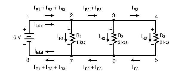
In a parallel circuit, components are connected across common points, providing multiple pathways for current to flow. The voltage across each component remains the same, while the current divides among the branches. Key features of parallel circuits include:
- Current: The current divides among the branches of a parallel circuit. Each branch may have a different resistance, resulting in different currents flowing through each component.
- Voltage: The voltage across each component remains the same as the total voltage of the source. This is because all components in a parallel circuit share the same two end points.
- Resistance: The reciprocal of the total resistance in a parallel circuit is the sum of the reciprocals of the individual resistances: 1total=11+12+…+1Rtotal1=R11+R21+…+Rn1.
- Brightness (for bulbs): In a parallel circuit, the bulbs have the same voltage across them, resulting in consistent brightness. If one bulb fails, the others remain unaffected.
- Redundancy and Reliability: Parallel circuits are more reliable since the failure of one component does not disrupt the entire circuit. Other components continue to function as long as the source voltage is maintained.
Applications:
- Series Circuits: Series circuits are often used in applications where the same current must flow through all components, such as in string lights and certain types of sensors.
- Parallel Circuits: Parallel circuits are widely used in household and industrial applications, including power distribution in homes, office buildings, and manufacturing facilities. They are also used in devices with multiple independent components like appliances and electronic gadgets.
In summary, series and parallel circuits offer distinct ways to configure electrical components, each with its advantages and applications. The choice between series and parallel connections depends on the specific requirements of the circuit and the desired behavior of the components.
Solving Complex Circuits
Solving complex electrical circuits involves applying various techniques and principles to analyze circuit behavior, calculate currents and voltages, and determine the responses of different components. Complex circuits can consist of multiple interconnected components, loops, and branches, and they often require systematic methods for accurate analysis. Here are some steps and techniques commonly used to solve complex circuits:
- Identify Circuit Components: Start by identifying all the components in the circuit, such as resistors, capacitors, inductors, and voltage/current sources. Label their values and polarities as necessary.
- Apply Kirchhoff’s Laws: Kirchhoff’s Current Law (KCL) and Kirchhoff’s Voltage Law (KVL) are fundamental tools for analyzing complex circuits. Apply KCL at nodes and KVL around closed loops to create equations that relate currents and voltages. These laws ensure that charge and energy conservation principles are followed.
- Simplify the Circuit: If the circuit is too complex, try to simplify it by combining resistors in series or parallel, reducing voltage sources to their equivalent values, or using delta-star transformations for resistor networks.
- Mesh and Nodal Analysis: For more complex circuits, consider using mesh analysis or nodal analysis. Mesh analysis involves defining loop currents and applying KVL to create a set of equations. Nodal analysis involves analyzing voltage at essential nodes using KCL.
- Superposition: If the circuit contains multiple independent sources, you can use the superposition principle to analyze the response of each source separately and then combine the results.
- Thevenin’s and Norton’s Theorems: These theorems help simplify circuits by replacing complex portions with equivalent circuits consisting of a single voltage source and resistor (Thevenin) or a current source and resistor (Norton).
- Circuit Symmetry: Exploit any symmetrical properties of the circuit to simplify the analysis. Symmetry often leads to equal currents, voltages, or resistance values in certain branches.
- Use Circuit Simulation Software: When dealing with very complex circuits, consider using circuit simulation software like SPICE. These tools allow you to model and simulate circuit behavior, helping to verify your calculations and predictions.
- Matrix Analysis: In more advanced circuits, matrix methods such as the nodal analysis matrix (Y-matrix) or the modified nodal analysis (MNA) can be employed to handle complex systems of equations.
- Solving Equations: Solve the derived equations using techniques like Gaussian elimination, matrix inversion, or computer software like MATLAB or Python.
- Check Consistency: After obtaining the solutions, ensure that the results are consistent with the fundamental principles of circuit analysis. Check if currents and voltages obey Ohm’s Law and Kirchhoff’s Laws.
- Iterative Approach: For circuits involving feedback loops or nonlinear components, an iterative approach might be necessary. This involves solving equations, updating values, and recalculating until the solution converges.
Solving complex circuits requires a combination of theoretical knowledge, problem-solving skills, and practical techniques. As circuits become more intricate, having a solid understanding of circuit analysis principles and access to tools and software can greatly facilitate the process and lead to accurate results.
Conclusion
Ohm’s Law and Kirchhoff’s Laws are foundational principles that form the backbone of electrical circuit analysis and design. These laws provide a comprehensive framework for understanding the behavior of electric currents, voltages, and components within circuits. Ohm’s Law, with its simple relationship between voltage, current, and resistance, serves as a guiding principle in predicting and controlling the behavior of circuits. It empowers engineers and enthusiasts to calculate, manipulate, and optimize circuit parameters for various applications.
On the other hand, Kirchhoff’s Current Law (KCL) and Kirchhoff’s Voltage Law (KVL) extend our understanding further by incorporating the principles of charge conservation and energy conservation, respectively. KCL enables us to analyze nodes and current flow, while KVL allows us to examine loops and voltage distribution. Together, these laws provide systematic methods for solving complex circuits and verifying the accuracy of our analyses.
The combined knowledge of Ohm’s Law and Kirchhoff’s Laws equips us to design, troubleshoot, and innovate within the realm of electronics. These principles are essential not only for engineers designing intricate circuits but also for anyone seeking to comprehend the interactions of electricity within various devices and systems. From basic circuits to sophisticated electronic systems, the applications of these laws are far-reaching, spanning industries and technologies that power our modern world. In embracing the insights offered by Ohm’s Law and Kirchhoff’s Laws, we unlock the potential to harness and manipulate electrical energy to drive innovation and shape the future of technology.